ALMA Common Software Architecture
COMP-70.25.00.00-002-F-DSN
Version: F
Status: Draft
2009-04-15
Prepared By: | ||
Name(s) and Signature(s) | Organization | Date |
G.Chiozzi | ESO | 2009-04-15 |
Approved By: | ||
Name and Signature | Organization | Date |
Released By: | ||
Name and Signature | Organization | Date |
Change Record
Version | Date | Affected Section(s) | Change | Reason/Initiation/Remarks |
1.0/Prep.1 | 11/20/99 | All | First revision for working group internal review [RD01] and has been used as an initial input for it. | |
1.0/Prep.2 | 01/15/00 | All | Updated after group internal review | |
1.1/Prep.1 | 05/31/00 | All | Updated after discussions with NRAO and meetings with G.Chiozzi, G.Raffi, and B.Glendenning. | |
1.1/Prep.2 | 06/10/00 | All | Document renamed ALMA Common Software [RD01] as an applicable document. | |
2.0/Prep.1 | 04/11/01 | All | Updated including all comment to issue 1.1/Prep.2 and results of Kitt Peak test and the feedback from the first experiences in the usage of the ACS 0.0 prototype. | |
2.0/Prep.2 | 09/10/01 | All | Updated taking into account document's review. | |
2 | 09/26/01 | Headers and footers | Assigned document number and released officially | |
3 | 11/15/02 | All | Document updated for ALMA Internal Design Review | |
3.1 | 02/14/03 | All | Document updated after ALMA Internal Design Review | |
A | 05/31/04 | All | Applied new ALMA Template Updated for CDR-2 | |
B | 05/16/05 | All | Updated for CDR-3 | |
C | 07/29/05 | All | Updated after CDR-3 | |
D-1.23 | 04/28/06 | All | Updated for CDR-4 | |
E-1.29 | 04/30/07 | All | Updated for CDR-5 | |
F-1.35 | 06/17/08 | All | Updated for CDR-6 | |
?? | 04/16/09 | All | Converted to OpenOffice, fixing various issues with graphics and header numbers | |
| ?? | 02/02/21 | All | Converted to confluence page |
Introduction
Scope
This document describes the architecture for the ALMA Common Software (ACS), taking as applicable the requirements specified in the ALMA Common Software Technical Requirements document
[RD01]
and the ALMA Software Architecture
[RD33]
. This document provides a complete picture of the desired ACS functionality for the entire development phase, but individual concepts and features will be developed incrementally over a number of releases, according to the ALMA Common Software Development Plan
[RD32]
. For each release, a detailed plan is developed, identifying the components to be added or revised. Development priorities will be discussed with the community of users during the planning phase of each release.
This issue of the Architecture takes into account the development of the ALMA Test Interferometer Control Software, the work done by the ALMA High Level Analysis team and the requests to ACS from higher level sub-systems as appearing in their respective documents and at the ACS planning meetings. In particular contains extensions that satisfy the needs of data flow software, pipeline, offline or proposal preparation. With version A of this document, it has been decided to use ACS also as the underlying framework for the offline data reduction package (AIPS++). This requirement widens the scope of ACS and introducing new requirements that cover in particular the following areas:
- Portability
The offline data reduction is supposed to be able to run on more platforms than the ones supported now by ACS for internal ALMA development and deployment. For example MacOS-X will have probably to be supported as well as a wider palette of Linux distributions.
- Start-up time
The offline data reduction package will be used as a stand alone package and reduction executable will need a short startup time compared to applications running all the time, where the startup time is therefore not relevant
- Modular installation
It will have to be possible to install on a target machine only the subset of ACS relevant for offline data reduction usage
- Static linking of components
It will have to be possible to execute specific data reduction pipelines as a single executable and not load dynamically components.
This version of the ACS Architecture addresses many of these issues.
This document describes also some features that have not been implemented for ALMA until now and that possibly will not be implemented. It has been decided not to remove their description from the document for completeness and to make clear what is foreseen if any of these extensions needs to be implemented. These features are clearly identified in the text by the "Not implemented yet" or "Implementation not foreseen for ALMA" strings and by the usage of different fonts.
Overview
ACS is located in between the ALMA application software and other basic commercial or shared software on top of the operating systems and provides a generalized common interface between applications and the hardware in order to facilitate the implementation and the integration in the system of new hardware and software components.
ACS provides basic software services common to the various applications (like antenna control, correlator software, data pipelining)
[RD01 - 3.1.1. Scope]
and consists of software developed specifically for ACS and as well of OS builds and commercial device drivers. All code specifically developed for ACS is under the GNU Lesser General Public License (LGPL)
[RD31]
. Commercial and off the shelf packages are subject to their specific license agreement.
ACS is designed to offer a clear path for the implementation of applications, with the goal of obtaining implicit conformity to design standards and maintainable software
[RD01 - 3.1.2. Design]
. The use of ACS software is mandatory in all applications, except when the requested functionality is not provided by ACS
[RD01 - 3.1.3. Use]
. Motivated exceptions (for example based on reuse considerations) have to be discussed and approved on a case by case basis.
The main users of ACS will be the developers of ALMA applications. The generic tools and GUIs provided by ACS to access logs, Configuration Database, active objects and other components of the system will be also used by operators and maintenance staff to perform routine maintenance operations
[RD01 - 3.2.1. Users]
.
This document identifies the main packages that will be part of ACS and their high level interrelations. For each package, a section in this document respectively discusses the requirements to clarify them and presents an architectural concept.
Requirements are traced back to the ALMA Common Software Technical Requirements document
[RD01]
whenever they are referenced. An ACS Requirements Compliance Table is maintained in the ACS Software Development Plan
[RD32]
.
The concept illustrated here is based on the use of CORBA and takes into account knowledge of various control software projects based on CORBA in the astronomical and High Energy Physics communities, like SOFIA
[RD10]
, GTC-Spain
[RD11]
, ESRFGrenoble
[RD03]
, ANKA-Kalsruhe
[RD04]
etc. A lot of experience has been accumulated in the past years of ACS development, in particular for what concerns the application of these concepts to high level applications and in particular pipeline, offline data reduction and observation preparation. A lot of discussions with the AIPS++ team have helped shaping ACS based on the requirements in these application domains. It has been an initial and explicit decision of the ALMA project to use CORBA technology and at the same time to share software rather than to re-invent it. It is up to documents like this to provide elements to confirm the initial choice of CORBA as adequate.
The reasons for using CORBA are in short: Object Orientation, support for distributed systems, platform independence, it is a communication standard, it provides a variety of services.
Reference Architecture
A reference layout for the system is provided by the ALMA Software
Architecture
[RD33]
, as required by
[RD01 - 2.3. Reference Architecture]
. The Architecture of the Test Interferometer is described in the TICS Design Concept document
[RD26]
.
For the purposes of this document a distributed architecture based on computers at the individual antennas and a number of central computers, connected by an high speed backbone
[RD01 - 10.4.3. LAN]
[RD01 - 10.4.4. Backbone]
[RD01 - 10.5.11. LAN]
, is assumed
[RD02]
.
At both the antenna and the central control building there will be not only Ethernet LAN connectivity but also a Field-bus
[RD01 - 10.4.5 Field-bus]
(the AMB)
[RD01 - 10.5.12. Field-bus]
connected to various intelligent devices. The fact that the Antenna controller and all or part of these Devices is on Field-bus or LANs shall not make any difference in terms of the architecture proposed here.
Pipeline, offline data reduction and other high level applications are also assumed to be distributed over many hosts, with the need or deploying CPU intensive applications dynamically based on the available resources.
Reference Documents
The reference documents contain background information required to fully understand the structure of this document, the terminology used, the software environment in which ALMA shall be integrated and the interface characteristics to the external systems.
The following documents are referenced in this document.
[RD01] ALMA Common Software Technical Requirements, COMP-
70.25.00.00-003-A-SPE, G.Raffi, B.Glendenning, J.Schwarz (<span style="color: #0000ff"><a href="http://www.eso.org/" class="external-link" rel="nofollow">http://www.eso.org/+</a></span>![]()
<span style="color: #0000ff"><span style="text-decoration: underline; ">~almamgr/AlmaAcs/MilestoneReleases/Phase1/ACSTechReqs/Issue1.0/2000-06</span></span>![]() <span style="color: #0000ff"><span style="text-decoration: underline; ">05.pdf</span></span>
<span style="color: #0000ff"><span style="text-decoration: underline; ">05.pdf</span></span>![]() )
)![]()
[RD02] ALMA Construction Project Book, Version 5.00, 2001-08-01 (![]() <span style="color: #0000ff"><a href="http://www.mma.nrao.edu/projectbk/construction/" class="external-link" rel="nofollow">http://www.mma.nrao.edu/projectbk/construction/+</a></span>
<span style="color: #0000ff"><a href="http://www.mma.nrao.edu/projectbk/construction/" class="external-link" rel="nofollow">http://www.mma.nrao.edu/projectbk/construction/+</a></span>![]() )
)![]()
[RD03] TANGO - an object oriented control system based on CORBA
J.M.Chaize et al., ICALEPCS'99 Conference, Trieste, IT, 1999
( <span style="color: #0000ff"><a href="http://www.elettra.trieste.it/ICALEPCS99/proceedings/papers/wa2i01.pdf" class="external-link" rel="nofollow">http://www.elettra.trieste.it/ICALEPCS99/proceedings/papers/wa2i01.pdf+</a></span>)
[RD04] Implementing Distributed Controlled Objects with CORBA - M.Plesko, PCs and Particle Accelerator Control Workshop, DESY, Hamburg, 1996
(See <span style="color: #0000ff"><a href="http://kgb.ijs.si/KGB/accomplishments_articles.php" class="external-link" rel="nofollow">http://kgb.ijs.si/KGB/accomplishments_articles.php+</a></span>[ |http://kgb.ijs.si/KGB/accomplishments_articles.php]for this and other related papers).
[RD05] SOSH Conventions for Control - F.DiMajoC.Watson, Software Sharing
(SOSH) for Accelerators & Physics Detectors (<span style="color: #0000ff"><a href="http://www.jlab.org/sosh/" class="external-link" rel="nofollow">http://www.jlab.org/sosh/+</a></span>)
[RD06] Java Home Page - (<span style="color: #0000ff"><a href="http://java.sun.com/" class="external-link" rel="nofollow">http://java.sun.com/+</a></span>)
[RD07] Real-time CORBA with TAO (the ACE ORB) -
(<span style="color: #0000ff"><a href="http://www.cs.wustl.edu/~schmidt/TAO.html" class="external-link" rel="nofollow">http://www.cs.wustl.edu/~schmidt/TAO.html+</a></span>)
[RD08] ObjectStore home page - (<span style="color: #0000ff"><a href="http://www.odi.com/objectstore/" class="external-link" rel="nofollow">http://www.odi.com/objectstore/+</a></span>)
[RD09] MySQL home page - (<span style="color: #0000ff"><a href="http://www.mysql.com" class="external-link" rel="nofollow">http://www.mysql.com+</a></span>)
[RD10] SOFIA home page - (<span style="color: #0000ff"><a href="http://sofia.arc.nasa.gov/" class="external-link" rel="nofollow">http://sofia.arc.nasa.gov/+</a></span>)
[RD11] GTC home page - (<span style="color: #0000ff"><a href="http://www.gtc.iac.es/" class="external-link" rel="nofollow">http://www.gtc.iac.es/+</a></span>)
[RD12] ALMA Monitor and Control Bus, Interface
Specification, ALMAComputing Memo #7, M.Brooks, L.D'Addario,Rev.B 200102-05
[RD13] National Instruments LabVIEW- (<span style="color: #0000ff"><a href="http://www.ni.com/labview/" class="external-link" rel="nofollow">http://www.ni.com/labview/+</a></span>)
[RD14] CORBA Telecom Log Service -
(<span style="color: #0000ff"><a href="http://www.omg.org/technology/documents/formal/telecom_log_service.htm" class="external-link" rel="nofollow">http://www.omg.org/technology/documents/formal/telecom_log_service.htm+</a></span>)
[RD15] omniORB Home Page - (<span style="color: #0000ff"><a href="http://www.uk.research.att.com/omniORB/" class="external-link" rel="nofollow">http://www.uk.research.att.com/omniORB/+</a></span>)
[RD16]OpenOrb Home Page - (<span style="color: #0000ff"><a href="http://openorb.sourceforge.net/" class="external-link" rel="nofollow">http://openorb.sourceforge.net/+</a></span>)
[RD17]ALMA SE Practices - Software Development Process Methodology
and Tools, G.Chiozzi, R.Karban, P.Sivera -
(<span style="color: #0000ff"><a href="http://www.mma.nrao.edu/development/computing/docs/joint/draft/SE" class="external-link" rel="nofollow">http://www.mma.nrao.edu/development/computing/docs/joint/draft/SE+</a></span><span style="color: #0000ff"><span style="text-decoration: underline; ">SwDev.pdf</span></span>)
[RD18] eXtensible Markup Language Home Page -
(<span style="color: #0000ff"><a href="http://www.w3.org/XML/" class="external-link" rel="nofollow">http://www.w3.org/XML/+</a></span>)
[RD19] CERN Laser project home page (<span style="color: #0000ff"><a href="http://proj-laser.web.cern.ch/proj" class="external-link" rel="nofollow">http://proj-laser.web.cern.ch/proj+</a></span><span style="color: #0000ff"><span style="text-decoration: underline; ">laser/</span></span>)
[RD20] IBM DB2 Home Page - (<span style="color: #0000ff"><a href="http://www-4.ibm.com/software/data/db2/" class="external-link" rel="nofollow">http://www-4.ibm.com/software/data/db2/+</a></span>)
[RD21] ALMA ACS and AMS Kitt Peak 2000 Test ,G.Chiozzi et al.
(<span style="color: #0000ff"><a href="http://www.mma.nrao.edu/development/computing/docs/joint/notes/2000-12" class="external-link" rel="nofollow">http://www.mma.nrao.edu/development/computing/docs/joint/notes/2000-12+</a></span><span style="color: #0000ff"><span style="text-decoration: underline; ">KP.pdf</span></span>)
[RD22]Design and Initial Implementation of Diagnostic and Error Reporting System of SMA, SMA Technical Memo 132, Q.Zhang.
[RD23] The Adaptive Communication Environment (ACE) home page -
(<span style="color: #0000ff"><a href="http://www.cs.wustl.edu/~schmidt/ACE.html" class="external-link" rel="nofollow">http://www.cs.wustl.edu/~schmidt/ACE.html+</a></span>)
[RD24] Python language home page - (<span style="color: #0000ff"><a href="http://www.python.org/" class="external-link" rel="nofollow">http://www.python.org/+</a></span>)
[RD25] Home Page for the Official Tcl/Tk Contributed Sources Archive - (<span style="color: #0000ff"><a href="http://www.neosoft.com/tcl/" class="external-link" rel="nofollow">http://www.neosoft.com/tcl/+</a></span>)
[RD26] Test Interferometer Control Software Design
Concept, B.Glendenning et al., DRAFT 2001-02-15
[RD27] Advanced CORBA Programming with C++,M.HenningS.Vinoski, Addison-Wesley, 1999
[RD28] ALMA Software Glossary, COMP-70.15.00.00-003-A-GEN
(<span style="color: #0000ff"><a href="http://www.alma.nrao.edu/development/computing/docs/joint/draft/Glossary.htm" class="external-link" rel="nofollow">http://www.alma.nrao.edu/development/computing/docs/joint/draft/Glossary.htm+</a></span>
)
[RD29] AMI/ACS Report, R. Lemke, G. Chiozzi 2001-03-20
(<span style="color: #0000ff"><a href="http://www.eso.org./projects/alma/develop/acs/examples/amitest/AmiReport.pdf" class="external-link" rel="nofollow">http://www.eso.org./projects/alma/develop/acs/examples/amitest/AmiReport.pdf+</a></span>)
[RD30] ALMA Memo #298, Timing and Synchronization, L. DÂ'Addario,
2000-03-09 (<span style="color: #0000ff"><a href="http://www.alma.nrao.edu/memos/html" class="external-link" rel="nofollow">http://www.alma.nrao.edu/memos/html+</a></span><span style="color: #0000ff"><span style="text-decoration: underline; ">memos/alma298/memo298.pdf</span></span>)
[RD31] GNU Lesser General Public License (GPL)
(<span style="color: #0000ff"><a href="http://www.gnu.org/copyleft/lesser.html" class="external-link" rel="nofollow">http://www.gnu.org/copyleft/lesser.html+</a></span>)
[RD32] ALMA Common Software Development Plan, COMP-70.25.00.00001-C-PLA (<span style="color: #0000ff"><a href="http://www.eso.org/projects/alma/develop/acs/Plan/index.html" class="external-link" rel="nofollow">http://www.eso.org/projects/alma/develop/acs/Plan/index.html+</a></span>)
[RD33] ALMA Software Architecture, ALMA-70.15.00.00-001-I-GEN,
J.Schwarz
(<span style="color: #0000ff"><a href="http://almaedm.tuc.nrao.edu/forums/alma/dispatch.cgi/Architecture/docProfile/10" class="external-link" rel="nofollow">http://almaedm.tuc.nrao.edu/forums/alma/dispatch.cgi/Architecture/docProfile/10+</a></span>
<span style="color: #0000ff"><span style="text-decoration: underline; ">0017/d20021117183329/No/ALMASoftwareArchitecture.pdf</span></span>)
[RD34]JacORB Home Page (<span style="color: #0000ff"><a href="http://www.jacorb.org/" class="external-link" rel="nofollow">http://www.jacorb.org/+</a></span>)
[RD35] Eclipse Home Page (<span style="color: #0000ff"><a href="http://www.eclipse.org/" class="external-link" rel="nofollow">http://www.eclipse.org/+</a></span>)
[RD36] Castor Home Page (<span style="color: #0000ff"><a href="http://castor.codehaus.org/" class="external-link" rel="nofollow">http://castor.codehaus.org/+</a></span>)
[RD37] OPUS Home Page (<span style="color: #0000ff"><a href="http://www.stsci.edu/software/OPUS/bb.html" class="external-link" rel="nofollow">http://www.stsci.edu/software/OPUS/bb.html+</a></span>)
[RD38] Rational Rose Home Page (<span style="color: #0000ff"><a href="http://www.rational.com/" class="external-link" rel="nofollow">http://www.rational.com/+</a></span>)
[RD39] Open ArchitectureWare project home page
(<span style="color: #0000ff"><a href="http://sourceforge.net/projects/architecturware/" class="external-link" rel="nofollow">http://sourceforge.net/projects/architecturware/+</a></span>)
[RD40] Java Web Start home page (<span style="color: #0000ff"><a href="http://java.sun.com/products/javawebstart/" class="external-link" rel="nofollow">http://java.sun.com/products/javawebstart/+</a></span>)
[RD41] ALMA Common Software home page
(<span style="color: #0000ff"><a href="http://www.eso.org/projects/alma/develop/acs/" class="external-link" rel="nofollow">http://www.eso.org/projects/alma/develop/acs/+</a></span>)
[RD42] CORBA Audio Video Streaming Service
(<span style="color: #0000ff"><a href="http://www.omg.org/technology/documents/formal/audio.htm" class="external-link" rel="nofollow">http://www.omg.org/technology/documents/formal/audio.htm+</a></span>)
[RD43] The design and performance of a CORBAAudio/Video Streaming
ServiceCORBA Audio Video Streaming Service , D.C.Schmidt et al.,
(<span style="color: #0000ff"><a href="http://www.cs.wustl.edu/~schmidt/PDF/av.pdf" class="external-link" rel="nofollow">http://www.cs.wustl.edu/~schmidt/PDF/av.pdf+</a></span>)
[RD44] ARCUS Error Handling for Business Information Systems, K.Renzel, sd&m Muenchen, 2003
(<span style="color: #0000ff"><a href="http://www.eso.org/~almamgr/AlmaAcs/OnlineDocs/ARCUSErrorHandling.pdf" class="external-link" rel="nofollow">http://www.eso.org/~almamgr/AlmaAcs/OnlineDocs/ARCUSErrorHandling.pdf+</a></span>)
[RD45] EVLA Engineering Software Requirement, B.Butler et. al. EVLA-SW004, Rev. 1.4, 2003
[RD46] EVLA Array Operations Software Requirements, J.Campbel et. al. EVLA-SW-003, Rev. 2.5, 2003
[RD47] JFreeChart (<span style="color: #0000ff"><a href="http://www.jfree.org/jfreechart/" class="external-link" rel="nofollow">http://www.jfree.org/jfreechart/+*</a></span>)
[RD48] MatplotlibJFreeChart
(<span style="color: #0000ff"><a href="http://matplotlib.sourceforge.net/installing.html" class="external-link" rel="nofollow">http://matplotlib.sourceforge.net/installing.html+*</a></span>) Glossary
An extended list of glossary definitions, abbreviations and acronyms is part of the main ALMA Software Glossary
[RD28]
, available online at the following URL: {+}http://www.mma.nrao.edu/development/computing/docs/joint/draft/Glossary.htm+.
The following list of abbreviations and acronyms is aimed to help the reader in recalling the extended meaning of the most important short expressions used in this document:ABM Antenna Bus Master ACE ADAPTIVE Communication Environment ({+}http://www.cs.wustl.edu/~schmidt/ACE.html+) ACS ALMA Common Software ACU Antenna Control Unit AIPS++ Astronomical Information Processing System ({+}http://aips2.nrao.edu/docs/aips++.html+) ALMA Atacama Large Millimeter Array ({+}http://www.eso.org/projects/alma/+) AMB ALMA Monitor and Control Bus ANKA Synchrotron Radiation Source ANKA ({+}http://www.fzk.de/anka+) API Application Programmatic Interface CAN Controller Area Network CORBA
Common Object Request Broker Architecture
COTS
Commercial Off The Shelf
CPU
Central Processing Unit
ESO
European Southern Observatory ({+}http://www.eso.org+)
FITS
Flexible Image Transport Format
GUI
Graphical User Interface
GTC
Gran Telescopio CANARIAS ({+}http://www.gtc.iac.es/+)
HW
Hardware
IDL
CORBA Interface Definition Language
IIOP
Internet Inter-ORB Protocol
ISO
International Standardization Organisation
JDBC
Java Database Connectivity
LAN
Local Area Network
LCU
Local Control Unit
M&C
Monitor and Control
N/A
Not Applicable
NRAO
National Radio Astronomy Observatory ({+}http://www.nrao.edu/+)
OMG
Object Management Group ({+}http://www.omg.org/+)
ORB
Object Request Broker
OSI
Open Systems Interconnection
OVRO
Owens Valley Radio Observatory ({+}http://www.ovro.caltech.edu/+)
RDBMS
Relational Data Base Management System
RPC
Remote Procedure Call
SLA
Subprogram Library A (Positional Astronomy Library)
SW
Software
TAO
The ACE ORB ({+}http://www.cs.wustl.edu/~schmidt/TAO.html+)
TBC
To Be Confirmed
TBD
To Be Defined
TCL
Tool Command Language ({+}http://www.scriptics.com/resource/+)
TCL
(CORBA)CORBA Trader Constraint Language
TICS
ALMA Test Interferometer Control Software
TPOINT Telescope Pointing Analysis System UML Unified Modeling Language URI Uniform Resource Identifier ({+}http://www.w3.org/Addressing/+) URL Uniform Resource Locator ({+}http://www.w3.org/Addressing/+) UTC Universal Time Coordinated VME Versa Module Eurocard VLT Very Large Telescope WS Workstation XML eXtensible Markup Language ({+}http://www.w3.org/XML/+) ACS Basic Architecture
Overview
The ALMA Common Software (ACS) is located in between the ALMA application software (Applications) and other basic commercial or shared software on top of the operating systems. In particular, ACS is based on CORBA (CORBA Middleware), which provides the whole infrastructure for the exchange of messages between distributed objects. Whenever possible, ACS features will be provided using off the shelf components and ACS itself will provide the packaging and the glue between these components.
The ACS is also based on an Object Oriented architecture[RD01 - 13.1.1 Distributed Objects and commands]
The following UML Package Diagram shows the main packages in which ACS has been subdivided.
Figure 2.1: ACS Packages
Each package provides a basic set of services and tools that shall be used by all ALMA applications.
Packages have been grouped in 4 layers. Packages are allowed to use services provided by other packages on the lower layers and on the same layer, but not on higher layers.
A 5th group contains packages for software that is used by many ALMA Subsystems, but that is not used by other ACS packages. These packages are for convenience integrated and distributed together with ACS but are not integral parts of ACS.
A brief description of the layers and the packages is provided hereafter, while the next chapter will contain a detailed description of the features included in the packages.
- - Base Tools
The bottom layer contains base tools that are distributed as part of ACS to provide a uniform development and run time environment on top of the operating system for all higher layers and applications. These are essentially off-the-shelf components and ACS itself just provides packaging and installation and distribution support. This ensures that all installations of ACS (development and run-time) will have the same basic set of tools with versions kept under configuration control.
The exact set of tools and versions are described in the documentation coming with each ACS release. Being these normally big packages the ACS installation procedures will have to offer the options of installing the tools in binary format, building them from sources or using an independent installation.
Three main packages have been identified in this layer:
- Development tools
Software development tools (compilers, configuration controls tools, languages, debuggers, documentation tools).
- CORBA Middleware
Packaging of off-the-shelf CORBA implementations (ORB and services) to cover the languages and operating systems supported by ACS.
- ACE
Distribution of the Adaptive Communication Environment
[RD23]
.
- - Core components
This second layer provides essential components that are necessary for the development of any application
- ACS Component
Base interfaces and classes for Component part of the ACS Component Model. In particular C++ Distributed Objects, Properties and Characteristics are implemented in this package.
- Configuration Database
Interfaces and basic implementation for the Configuration Database from where ACS Components retrieve their initial configuration
- Event and Notification System
The Event and Notification System provides a generic mechanism to asynchronously pass information between data publishers and data subscribers, in a many-to-many relation scheme.
- Error System
API for handling and logging run-time errors, tools for defining error conditions, tools for browsing and analyzing run-time errors.
- Logging System
API for logging of data, actions and events. Transport of logs from the producer to the central archive. Tools for browsing logs.
- Time System
Time and synchronization services.
- - Services
The third layer implements services that are not strictly necessary for the development of prototypes and test applications or that are meant to allow optimization of the performances of the system:
- ACS Container
Design patterns, protocols and high level services for Component/Container life-cycle management.
- Serialization Plugs
This package provides a generic mechanism to serialize entity data between high level applications, typically written in Java.
- Archiving System
API and services for archiving monitoring data and events from the run time system. Tools to browse, monitor and administer the flow of data toward the archive.
- Command System
Tools for the definition of commands, API for run-time command syntax checking, API and tools for dynamic command invocation.
- Alarm System
API and tools for configuration of hierarchical alarm conditions, API for requesting notification of alarms at the application level, tools for displaying and handling the list of active alarms.
- Sampling
Low level engine and high level tools for fast data sampling (virtual oscilloscope).
- Bulk Data
API and services for the transport of bulk science data (images or big data files) and continuous data streaming.
- - API and High-level tools
The fourth and last layer provides high level APIs and tools. More will be added in the future. The main goals for these packages is to offer a clear path for the implementation of applications, with the goal of obtaining implicit conformity to design standards and maintainable software
[RD01 - 3.1.2. Design]
.
- UIF Libraries
Development tools and widget libraries for User Interface development .
- Parameters
Support libraries and classes for "parameter sets", i.e support for definition, parsing and validation of sets of parameters, plus some additional metadata such as help information, valid ranges, default values, whether the parameters are required or optional, etc.
- Task
A task is a concise program which starts up, performs some processing, and then shuts down. A task may or may not require other more advanced ACS services, depending on context.
- Scripting
Scripting language and access libraries for the integration with ACS core components.
- ACS Application Framework
Implementation of design patterns and to allow the development of standard C++, Java and Python applications using ACS services.
- ACS Installer
Tolls for installing ACS with different options.
- - Integrated APIs and tools
The 5th group of packages contains software that is used by many ALMA Subsystems, but that is not used by other ACS packages. These packages are for convenience integrated and distributed together with ACS but are not integral parts of ACS. The list of packages will be extended according to the ALMA integration needs. If considered useful, some packages can be hidden on the back of an ACS abstraction layer with the purpose of facilitating the usage of the package and its integration with other ACS facilities (like error and alarm handling). In this case the package would be moved in layer 4 of the ACS architecture.
- Device Drivers
Low-level device drivers for commonly used devices
- Astronomical libraries
Libraries for astronomical calculations and data reduction.
- External libraries
Support for the handling of FITS files is just an example of other highlevel components that will be integrated and/or distributed as part of ACS.
2.2Component Container model
The Technical Architecture in the ALMA Software Architecture document
[RD33]
identifies a Container-Component model for software organization and development as our primary instrument for achieving separation of functional from technical concerns.
A Component is defined in
[RD33]
as a software element that exposes its services through a published interface and explicitly declares its dependencies on other components and services, can be deployed independently and, in addition:
- "is coarse grained: In contrast to a programming language class, a component has a much larger granularity and thus usually more responsibilities. Internally, a component can be made up of classes, or, if no OO language is used, can be made up of any other suitable constructs. Component based development and OO are not technically related."
- "requires a runtime environment: A components cannot exist on its own, it requires something which provides it with some necessary services." This "something" is called a Container.
- "is remotely accessible, in order to support distributed, component based applications."
The division of responsibilities between Components and Containers enables decisions about where individual components are deployed to be deferred until runtime. If the container manages component security as well, authorization policies can be configured at run time in the same way.
A Component is required to provide:
- a Lifecycle interface, so that the Container where it resides can manage it
- a Service interface, that is the interface it exposes to clients
Architecture
A Container is required to provide:
- an implementation for all basic services used by the Components
- a ContainerServices interface used by the Components to get access to the services
ACS provides a simple implementation of the Component-Container model implemented in C++, Java and Python.
In order to decouple the Component and Container implementations, the ACS Component package contains the definition of all the interfaces needed for the implementation of Components and the default implementation of the interface which can be used as base classes for the Components themselves.
The ACS Container package contains the actual implementation for the Container model, including the high level management of Containers (Manager). The following diagram provides an overview class diagram of the ComponentContainer model. More details are given in the description of the Component and Container architectural packages.
Architecture
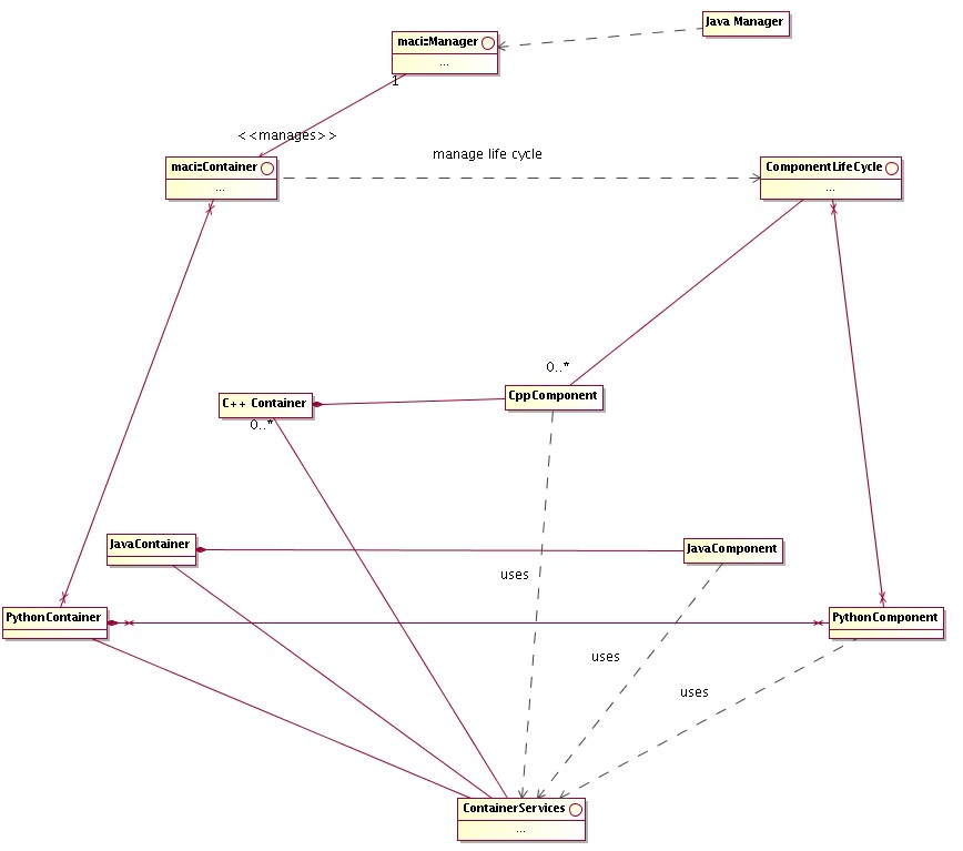
Figure 2.2: ACS Component-Container overview class diagram
For a more detailed discussion of rationale behind the choice of the ComponentContainer model, see the ALMA Software Architecture document
[RD33]
.
2.3Deployment
The choice of CORBA for the implementation of a Component/Container model and of all services that are part of the previously described packages makes it possible to have every software operation available in a transparent way both locally and at the Control Center in San Pedro. This applies also to all data, logs and alarms
[RD01 - 12.1.6 Location]
. The choice for the LAN and access optimization mechanisms, described in the following sections, will ensure that no significant degradation in performance will take place
[RD01 - 3.2.4. Local and central operation]
.
In principle, this same mechanism allows reliable remote access from the US and Europe, although with reduced performance. It is anyway necessary that applications are designed in order to prevent unauthorized access and undesired side effects on the performance of the control system
[RD01 - 3.2.5. Remote access]
. ACS provides the basic building blocks for the implementation of these mechanisms.
All packages in the lower ACS layers are available for developing code both for the Linux
[RD01 - 10.5.4 OS]
and the VxWorks
[RD01 - 10.5.3 RTOS]
platforms. The usage of the ACE C++ toolkit allows writing portable code that can migrate, for example, from Linux to VxWorks and vice versa according to development and run-time needs.
Real Time Linux has replaced VxWorks as the real time development platform in ALMA (limited support for VxWorks is maintained for other projects). In this configuration, only hard real time tasks will run in the real time kernel, while every other task will run in the normal Linux kernel. ACS provides "bridge modules" that allow the real time tasks to communicate with non real time tasks in a standard way. For example, a logging "bridge module" allows the generation of logs on the real time side and their further propagation on the non real time side.
Higher-level components are not usually needed on the real-time platform. In this case Java will be used to provide portability among non real-time platforms (for example Linux and Windows). This will apply in particular for user interface applications.
Some development tools can be required to run or can be more convenient to use on Windows platforms.
Via CORBA, all objects publishing an IDL interface will be available to any environment, host and programming language where a CORBA implementation is available. In particular it will be possible to write client applications for
Components in any CORBA-aware platform. ACS explicitly supports C++, Java, C and Python
[RD01 - 10.3.3. Compiled Languages]
[RD01 - 10.5.6. Scripting language].
The ACS Component/Container model is then implemented in C+, Java and Python. The three implementations are not identical, but are tailored to the specific application domain of the language. For example, the C+
implementation provides strong support for the
Component/Property/Characteristic pattern of interest for Control Applications
Architecture
and provides a more sophisticated threading model handling of interest for the Pipeline and Offline Data Reduction applications. On the other hand, the Java implementation provides Tight Containers and transparent XML serialization.
The ACS installation procedures will allow selecting the installation platform and will allow selecting between development and run time installations. For a development installation, all development tools will be installed, including compilers and debuggers, while a run-time installation will be much lighter and include only the libraries and components needed at run-time. There is also a separate installation for "pure Java" applications that will be installable and usable from any machine supporting a Java Virtual Machine. This is based on Web Start technology to make installation as simple and automatic as possible, as well as software upgrades.
Per each package, it will be specified at design time what components will be available on each platform and for run-time and development installations.
We foresee 7 different types of deployment nodes (connections in the diagram show the foreseen communication paths among node types, for example a Remote User Station is allowed to communicate only with a Linux run-time workstation):
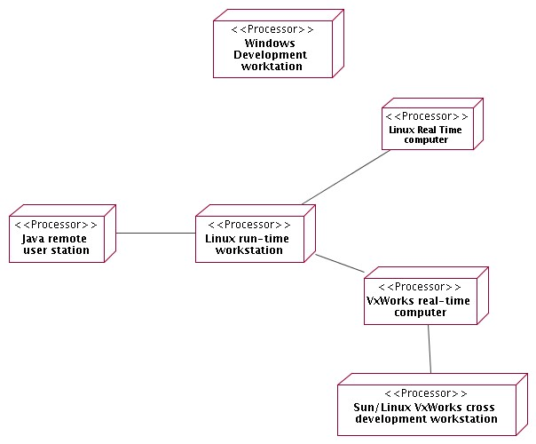
Figure 2.3: ACS Deployment
- Linux Development workstation
Linux is the main development and run-time platform.
This installation includes all ACS components necessary for development and at run-time.
- Windows Development workstation
Windows is a development and run-time platform for Java based applications and user interfaces. In some cases and in particular for very high level tools that have to be installed on the premises of astronomers, it is explicitly required that they be supported on various platforms. Developing not only from a Linux but also from a Windows environment would help in ensuring better compliance with Java Virtual Machines on various platforms.
An ACS Windows Development installation will allow installing Java development tools and Java libraries for development, including CORBA ORB and services.
We assume that an ACS developer will have a Windows desktop used for
Java development and as a terminal to connect to a Linux Development Workstation. This does not exclude users having access only to Linux workstations but limit their capability and/or comfort in developing Java applications.
- Linux Real Time Computer
Linux real time computers can be normal PCs or VME racks with Intel CPU running a real time Linux kernel.
- Linux run-time workstation
When disk space is an issue for small run-time only boxes, it will be possible to deploy on ACS runtime libraries and components. The main limitation of this configuration is that it offers very poor debugging capabilities in case of problems, with respect to a full development installation
- Remote user station
A very light ACS installation will be provided for users that need only to run Java/Python applications to remotely interact with other ALMA subsystems. This will allow installing only Java/Python ACS run time libraries and applications (including CORBA ORB and services) on Linux, Windows or other operating systems supporting a Java Virtual Machine (officially supported and tested Java Virtual Machines will be defined at each ACS and specific application release) or a Python interpreter.
- VxWorks real-time computer (not used in ALMA)
VxWorks computers are used only as run time platforms, as a crossdevelopment computer is necessary to develop code. ACS will deploy on VxWorks only run time libraries, which are downloaded from a file server at boot time or when needed.
VxWorks computers have been phased out from ALMA and replaced by computers running a real-time Linux kernel.
- Linux VxWorks cross-development workstation
The VxWorks cross development environment is installed on a Linux workstation. This includes all development tools and ACS components. Typically the same development workstation should be used for Linux and VxWorks development. We are constrained by the fact that WindRiver does not support Linux as a VxWorks cross-development environment for the version of VxWorks we support in ACS. We have now a cross development environment for Linux, but we cannot run Wind River debugging and development tools there. Therefore we use normally Linux for cross-development, but it might be convenient to keep available Sun workstations when we need to run Wind River development tools. Sun has been phased out from ALMA together with VxWorks.
3ACS Packages
This chapter contains one section per each ACS package, describing the features provided and its high level architecture.
The packages are described, looking at the package diagram in Chapter 2, starting from the lower layer and from left to right.
For some packages, just a brief description is given. In particular this applies to packages that are just the integration of off the shelf components.
3.1Development tools
Packaging of tools necessary for the whole life cycle of software developed with ACS. This includes for example compilers, configuration controls tools, languages, debuggers, documentation tools and general purpose class libraries. The complete list will be defined at each release. ACS will assume a specific set of supported Operating Systems and versions.
3.2CORBA Middleware
Packaging of off-the-shelf CORBA implementations (ORB and services) to cover the languages and operating systems supported by ACS.
This includes also all CORBA Services used by ACS.
The complete list of ORBs and Services will be defined at each release. The ACS distribution contains the binary version of the ORBs and Services and allows rebuilding the binaries from sources. Whenever possible the original distribution from the vendor, in the right versions, is provided; in some case specific ACS patches are distributed together with the original distribution.
3.3ACE
Distribution of the Adaptive Communication Environment
[RD23]
. This C++ class library provides support for cross-platform portability and implementation for a wide set of design pattern specific for distributed systems.
3.4ACS Component
The requirements document
[RD01]
specifies as a basic design requirement the adoption of an Object Oriented architecture based on distributed objects
[RD01 - 13.1.1 Distributed Objects and commands]
.
The Technical Architecture in the ALMA Software Architecture document
[RD33]
identifies a Container-Component model for software organization and development as our primary instrument for achieving separation of functional from technical concerns.
This concept is the basis for the architecture and all services provided by ACS are designed around Components.
3.4.1 Every Component must implement the ComponentLifeCycle interface. This interface foresees the following basic lifecycle operations:
- initialize – called to give the component time to initialize itself, e.g.
retrieve connections, read configuration parameters, build up in-memory tables…..
- execute – called after initialize() to tell the component that it has to be ready to accept incoming functional calls any time
- cleanup – the component should release resources in an orderly manner, because shutdown is imminent
- aboutToAbort – the component will be forcibly removed due to some error condition.
3.4.2The Container passes to each Component a ContainerServices object (in C++ this occurs at construction time, while in Java at initialize() time, because of the different traditional ways of using constructors and destructors in the two languages). At that point, the Component can assume that all infrastuctural services it may need have been properly set up by the Container and are available via the ContainerServices object.
3.4.3The architecture of the system is based on CORBA. Component and Container interfaces are described in IDL, and Components and Container are implemented as CORBA objects. The impact of CORBA on component implementation classes is very low or none, varying among languages.
3.4.4For exceptional cases, a component can explicitly ask the container to create an associated CORBA object (called an "OffShoot") and then pass it around in the system.
3.4.5ORB independence and interoperability
[RD01 - 10.4.2 ORB Independence]
is ensured by basing the Distributed Object implementation on CORBA Inter-ORB
Protocol (IIOP) and Portable Object Adapter (POA) and by not allowing the use of any ORB-specific feature. Interoperability between ORBs has been demonstrated with the the Kitt Peak Test and with the previous releases of ACS, where we have changed ORBs a number of times. The selection of the final ORBs needed for ACS is not part of this Architecture document. The current baseline includes TAO
[RD07]
for C/C++, JacORB
[RD34]
for Java, omniORB
[RD15]
for Python bindings, OpenOrb
[RD16]
for some code generation tools.
3.4.6ACS provides a C+, a Java, and a Python Container Implementation. The three implementations differ in the features offered because C+, Java and Python applications have different requirements, as described in
[RD33]
. Features from one type of component can be implemented also for the other type, if the requirement arises.
3.4.7ContainerSercices and ComponentLifeCycle interfaces are NOT defined as IDL interfaces, since they are used only in the internal communication between Components and Containers and there are language specific differences.
3.4.8Basic functionality provided by ContainerServices is:
- getName()
- getComponent(name)
- findComponent(type)
- releaseComponent(name)
- getCDB()
- getThreadManager()
For more details see the implementation and detailed design documentation. In particular there are various flavours of the getComponent() interface, some described here after.
3.4.9Specific Containers can provide specialised subclasses of ContainerServices with additional features. Components aware of this additional functionality can make use of it, while other Components would ignore it transparently.
3.4.10 Normally a Container will provide each Component with a specific instance of ContainerServices that contains specific context information, but this is left to the responsibility of the Container. Therefore the life cycle of the ContainerServices objects is left to the complete control of the Container.
--------------------------------------------------
3.4.11 Characteristic Components are a subclass of Components tailored to the implementation of objects that describe collections of numerical (typically physical) quantities. They have been designed in particular to represent Control
System objects with monitor and control points or objects with state and configurable parameters. In particular Characteristic Components are described using a 3 tier naming for the logical model
[RD03]
[RD04]
[RD05]
:
- Characteristic Component
- Property
- Characteristic
3.4.11.1 Characteristic Component - Instances of classes identified at design level in the ALMA system, with which other components of the system interact, are implemented as Characteristic Components. In particular, at control system level, Characteristic Component is the base class used for the representation of any physical (a temperature sensor, a motor) or logical device in the control system. Higher level applications can use Characteristic Components to implement any Component that has configurable values representing numerical quantities.
3.4.11.2 Property - Each Characteristic Component has 0..n Properties that are monitored and controlled, for example status, position, velocity and electric current.
3.4.11.2.1 Properties can be read-only or read/write. If a read/write property cannot read its value back (for example it is associated with a write-only physical device), it caches the last written value and returns this upon read request. This implementation is mandatory and must be documented in the property documentation.
3.4.11.2.2 Properties can represent values using a limited set of basic data types:
- long, longLong and uLongLong for integers • double for floating point numbers
- string for strings.
- pattern to handle patterns of bits, typically from hardware devices
- enum for enumerations like states. This includes a boolean TRUE/FALSE enumeration.
- sequence<scalar property> of one of the previously defined scalar property types. A Sequence<scalar property> is a sequence (in CORBA IDL terms) of properties of a given scalar type, i.e. each item in the sequence is a complete property of the given scalar type. It is implemented as an IDL Sequence of the scalar property type. For example a sequence<long> allows manipulating a group of properties of type long. Each item in the list can be assigned to a long property object and manipulated (reading characteristics and value) independently from the others.
- scalarTypeSeq of one of the previously defined scalar types. A scalarTypeSeqis a property type that contains as value an array of values handled by the corresponding scalar type. For example, a longSeq is a property type with a single set of characteristics that apply to an array of integers. It is a single property and its value is an array of values. With respect to sequence<scalar property>, scalarTypeSeq is much more efficient for transporting big tables of data. (Not all types implemented for
ALMA)
- complex for handling complex numbers (Implementation not foreseen for ALMA)
- structures built with properties of the other basic types. Since structures introduce a significant increase of complexity in the handling libraries, they will be implemented last and only if a clear need arises.(Implementation not foreseen for ALMA)
3.4.11.2.3 The selection of a limited set of type is motivated by the need of avoiding implementing the same code for many different types and conversion problems between similar types (like short, int and long). Also, nowadays saving a couple of bytes using a short instead of a long usually introduces performance problems (CPUs now always works with longs and every operation on a short requires a conversion to long)
3.4.11.3 Characteristic - Static data associated with a Characteristic Component or with a Property, including meta-data such as name, description, version and dimensions, and other data such as units, range or resolution. Each Characteristic Component or each Property has 0..n Characteristics.
An initial list of Characteristics for Characteristic Components and Properties has been agreed and more details are given in the design documentation:
- Characteristic Components and Properties: Name, Description, Version and URI of extended documentation, where the last is optional and would point to documentation generated automatically from the source code.
- Read-only and Read/Write Properties: default values, range, units, format, resolution
3.4.11.4 The following diagram shows an architectural class diagram for the Characteristic Component - Property - Characteristic pattern
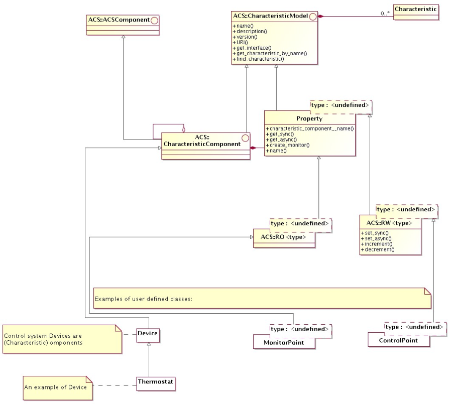
Figure 3.1: Characteristic Component - Property - Characteristic class diagram
- The diagram shows the classes that have an IDL public interface and is not concerned with actual implementation of the servants that realize these interfaces.
- A CharacteristicModel base interface class groups methods and attributes common to both Property and Characteristic Component. In particular, both have a common set of Characteristics and provide the related access methods.
- A Characteristic Component can reference other Characteristic Components, to build a hierarchical structure
- Properties are always contained into a Characteristic Component. This means that a Characteristic Component can contain 0 or many Property instances, while a property is always contained in one and only one Characteristic Component. The Property class provides a method to retrieve the reference to the Characteristic Component that contains it.
- From the base Property class, subclasses for each read only and read/write types are derived. This is represented in the diagram by the ROProperty<type> and RWProperty<type> parametrized classes. From an architectural point of view, RWProperty<type> classes are subclasses of the corresponding ROProperty<type>.
- The lower part of the diagram (white class boxes) shows how applications will inherit from the base classes provided by ACS. The example shows classes used for the implementation of the control system.
- This diagram is sufficient and correct at architecture level. At design level, we have introduced some intermediate class levels to improve the modularity of the code. These intermediate classes are in any case hidden to the users, making the actual structure between the Property class and the implementation of RO and RW properties an implementation detail.
3.4.11.5 At the servant's implementation level, the classes implementing the Property interfaces are responsible for the actual interfacing with the hardware or, more in general, to retrieve/calculate the value for the numerical entities. In order to decouple as much as possible the implementation of Property classes and the access to different kinds of data sources, we have parametrized the default Property implementation provided by ACS with a DevIO parameter, as shown in the following class diagram. A DevIO implementation is responsible only for reading/writing the Property's value from a specific device (memory location, CAN bus, Socket connection, serial port, database….), therefore in most cases access to a new kind of device can be implemented just by implementing a new DevIO class. In more complex cases or for performance optimization it may be necessary to re-implement the entire Property interface.
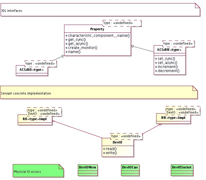
Figure 3.2: Property Servant Implementation class diagram
3.4.11.6 Another common strategy to handle the case where a data source produces simultaneously the values for many Properties consist in mapping the Properties onto memory-based DevIOs and let a parallel execution thread update all memory locations from the data collected with one single access to the data source.
3.4.11.7 The Characteristic Components - Properties - Characteristics 3 tier logical model is very well established in the community of Control Systems for Physics Experiments
[RD03]
[RD04]
[RD05]
, where the name Device is used to identify what we call here Characteristic Component. We prefer to adopt the more generic name, as specified in
[RD01 - 13.1.1 Characteristic Components and Commands]
, because the usage of the ACS is not limited to the realm of the Control System, as in the case of the mentioned references. It provides instead generic services for the development of the whole ALMA software. Proper Device classes are implemented by the Control System development team based on Characteristic Components.
3.4.12 The Characteristic Component model is based on CORBA:
3.4.12.1 A Characteristic Component is a CORBA object
3.4.12.2 A Property is a CORBA object. A class hierarchy with Property class as root implements the basic read-only and read/write versions for the predefined types. This hierarchy provides standard IDL interfaces that shall be used by all clients to access Properties. On the implementation (servant) side, specific subclasses will provide polymorphic access to specific implementations like 'logical', 'simulated', 'CAN', 'RS232', 'Digital IO' and so on.
3.4.12.3 Public interfaces to Characteristic Components and Properties are defined as
CORBA IDL.
3.4.12.4 Characteristics of Characteristic Components and Properties can be accessed through access methods (as shown in figure) and through a generic value = get_characteristic_by_name(name) type of interface at run time. The interface of properties is defined by their IDL and the IDL is the same independently from the implementation (logical, CAN...). But specific implementations will have also specific characteristics. For example a CANLong property has a CANID characteristic. This means that from the property's IDL there is no way to retrieve the CANID using CORBA calls. We provide then a generic interface that can be used to retrieve any characteristic just querying by name. This allows accessing specific Characteristics, like the CAN ID for properties related to CAN monitor points that are not defined in the generic property IDL but are instead implementation specific.
3.4.13 The configuration parameters for all Characteristic Components, i.e. the initial
values for Properties control values and all Characteristics for Properties, are persistently stored in the Configuration Database
[RD01 - 4.2.1. Configuration Database]
. See the section on Configuration Database architecture.
3.4.14 Characteristic Components may have a state. Specific Characteristic Components can have additional sub-states.
[RD01 - 13.1.2 Standard Methods]
[RD01 - 14.1.13 States]
.
3.4.15 Note: A standard state machine and standard state transition commands could be defined. (Implementation not foreseen for ALMA).
3.4.16 JavaBeans wrap CORBA objects on the client side. Standard Rapid Application Development (RAD) tools like Eclipse
[RD35]
are used to handle them. Given the IDL interface of a Characteristic Component, a code generator automatically produces the corresponding JavaBean. In this way the developer has libraries that provide him direct support for ACS concepts like Characteristic Component/Property/Characteristic, Monitors, and Event and Notification System.
3.4.17 ACS also provides a generic IDL simulator (see section IDL Simulator) to simulate an entire Component.
3.4.18 If an application wants to provide a more sophisticated level of simulation (for
example simulating interrelations between the values of properties), a specific
simulated device should be implemented in parallel to the real device. Switching from the real to the simulated device is handled in the configuration of the Manager (see Management and Access Control section), telling it to start a different implementation of the same device's CORBA interface.
3.4.19
Note: As an extension, ACS could provide support for simulation[RD01 - 3.3.4.
Simulation] at Property level. All properties that access hardware can be switched in simulation by setting TRUE a simulation characteristic in the configuration database. After this, they behave like "logical properties". This provides basic simulation capabilities. (Implementation not foreseen for ALMA).
3.4.20 Direct Value Retrieval
3.4.20.1 The Property classes provide get() and, in case of writeable Properties, set() methods that can be used to directly access the value of the property from clients
[RD01 - 4.1.1 Direct value retrieval]
. Both synchronous and asynchronous get() and set() methods are provided.
3.4.20.2 Value setting is done using set() property methods. These methods can be called by applications or by specifically designed GUIs. CORBA Dynamic Invocation Interface allows to write generic applications and GUIs (like the Object
Explorer) that are capable of resolving dynamically at run time the structure of Characteristic Components and call set() methods to set the value of Properties
[RD01 - 3.2.3. Value setting]
.
3.4.20.3 DevIO specialization is used to implement properties accessing specific hardware devices, like CAN, RS232, GPIB. CAN properties will always directly access the hardware on the CAN bus at direct value retrieval and not use cached values.
3.4.21 Value Retrieval by Event
3.4.21.1 The Characteristic Component provides a method to create a monitor object for a Property, able to trigger events on Property change or periodically. A callback will be connected to the event and will be called by the monitor object when the specified event occurs
[RD01 - 13.1.4. Events]
. Triggered events are delivered directly to the registered object via the callback mechanism in a point-to-point fashion. The value retrieval by event is then very well suited for providing timely feedback to control applications.
3.4.21.2 Events can be generated on any change of value
[RD01 - 4.1.3 Rate]
.
3.4.21.3 Note: Other conditions, for example any write, value increase/decrease, value less or greater than set-point could also be included at a later stage. (Implementation not foreseen for ALMA)
3.4.21.4 Timed or periodic events can be generated as follows:
Periodic, at a specific interval rate
[RD01 - 4.1.3 Rate]
Periodic, at a specific interval rate, synchronized with an absolute array time
[RD01 - 4.1.5 Values at given time]
. This also allows periodic events aligned with the monitoring rate. For example, a 1-second rate generates events on the 1-second mark, 5-second rate on the 5-second mark and so on.
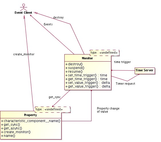
Figure 3.3: Value Retrieval by Event: ACS Monitors
3.4.21.5 All events will be time stamped with the time at which the value has been acquired (as opposed to the time of delivery of the event). Timed events will be triggered "timers" such that the requested time is the time of acquisition of the value, and not the time of delivery which depends on the network characteristics.
3.4.21.6 The monitor class provides methods to suspend, resume and destroy the monitor
itself.
3.4.21.7 Note: CAN-Properties will have to implement notification on change also for CAN
monitor points although CAN monitor points do not provide a specific support via HW or in the drivers. This can/should be done via polling. If there are clients registered on events on change, an ACS monitor is used to poll and to generate events in case of change of the value of the monitor point. The poll rate is defined by the characteristic change frequency. The polling frequency determines the time resolution of the eventon-change. (implementation not foreseen for ALMA)
3.4.21.8 Note: For performance optimization, the final implementation will not leave to the single Characteristic Component Properties the responsibility of managing timers, but a local centralized manager will take care of that, transparently to client applications. More details will be given in the ACS design. (implementation not foreseen for ALMA)
3.4.21.9 Note: A particular case is a Characteristic Component State Machine. A State Machine class is a Characteristic Component and the current state is represented by a State Property. This State Property can fire events whenever the state changes to allow external objects to monitor it. (implementation not foreseen for ALMA)
3.4.22 Supported implementation languages
The Characteristic Component / Property /characteristic pattern is implemented in C++ and in Java and Python
Note: Java and Python implementations are not complete and contain now all and only the features used in ALMA.
--------------------------------------------------
3.4.23 ACS Java Components provide explicit support for the transparent serialization of instances of entity classes
[RD01 - 3.3.2. Serialization]
. See the section on "Serialization".
3.5Configuration Database
3.5.1The configuration parameters for all Components and, in particular, for all
Characteristic Components, i.e. the initial values for Properties values and all
Characteristics for Properties, are persistently stored in the Configuration Database
[RD01 - 4.2.1. Configuration Database]
. Any application can make use of the Configuration Database to get access to configuration information.
3.5.2 There are 4 different issues related to the problems addressed by the CDB:
- input of data by the user
System configurators define the structure of the system and enter the configuration data. Easy and intuitive data entry methods are needed.
- storage of the data
The configuration data is kept into a database.
- maintenance and management of the data (e.g. versioning) Configuration data changes because the system structure and/or the implementation of the system's components changes with time and has to be maintained under configuration control.
- loading data into the ACS Containers
At run-time, the data has to be retrieved and used to initialize and configure the Components.
The main objective of the CDB Architecture is to keep these 4 issues as decoupled as possible so that:
- We can develop them separately, in space and time, according to the project priorities and the availability of resources.
- We can eventually use different technologies
- We can, in particular, support multiple data storage mechanisms (like ALMA Archive, RDBMS and XML files) in different environments (development, testing, final running system).
3.5.3The high-level architecture is based on three layers:
- The Database Itself
It is the database engine we use to store and retrieve data.
- The Database Access Layer (DAL) is used to hide the actual database implementation from applications, so that it is possible to use the same interfaces to access different database engines, as described in the requirements and discussed in the following sections.
- The Database Clients, store and retrieve data from the database using only the interfaces provided by the DAL.
Data Clients, like containers, Managers and Components retrieve their configuration information from the Database and are involved in issue 4. On the other hand, CDB Administration applications are used to configure, maintain and load data in the database using again interfaces provided by the DAL layer. They are involved in issue 1 and 3 and will be possibly using DAL interfaces different from the ones used by the Data Clients, as will be discussed later on.
Notice that Data Clients need only data retrieving and not data change functions.
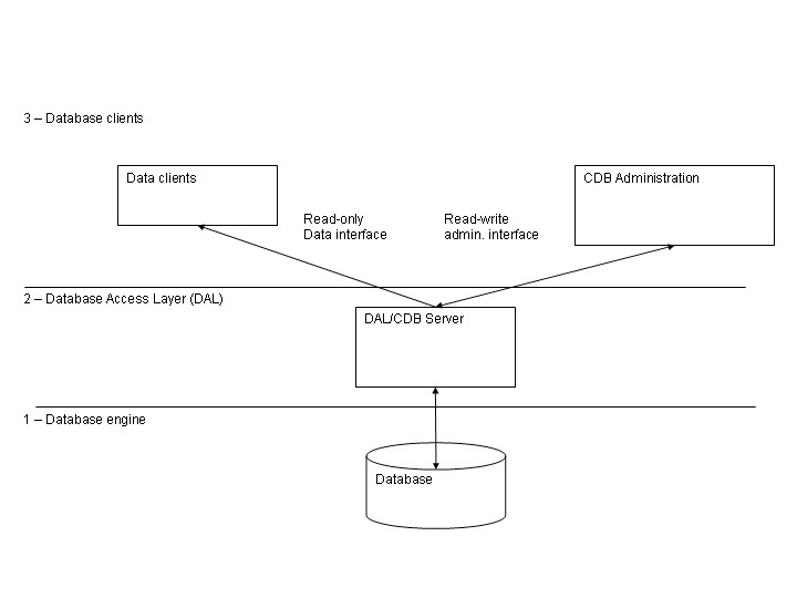
Figure 3.4: Configuration Database architectural layers
3.5.4A Database Loader application is used to manipulate database description files and load them into the Database using the DAL administrator interfaces. Database Description Files are XML files and XML Schemas are used to define classes of database entities, allowing to use inheritance and to define default values. The Database Loader also takes care of validating the data, to make sure that only valid and consistent data is actually loaded into the database. For example, the following inconsistencies should be spotted and reported:
- missing property or characteristic
- undefined values, default will be used
- defined values that are not used elsewhere
3.5.5 When a Characteristic Component is instantiated, it configures itself according to the configuration stored in the Configuration Database
[RD01 - 3.3.2. Serialization]
.
3.5.6The implementation of the Configuration Database is hidden in a Configuration Database Access API to allow switching among alternative implementations
[RD01 - 4.2.2 Database Design]
.
3.5.7The reference implementation is based on XML files and a Java application loads and parses the XML files. Files are validated at run time and a separate CDB checker can be used to validate offline CDB XML files without the need of loading them in a "live" database.
3.5.8In ALMA, configuration information is stored in the Telescope and Monitoring Configuration Data Base (TMCDB). This is based on the Oracle RDBMS (with the small-footprint RDBMS, hsqldb, used for small-scale testing). Archive, Control and ACS subsystems are responsible for the implementation of the Configuration Database Access API on top of the TMCDB, throught the implementation of a specific Component. This implementation includes roundtrip tools to convert CDB instances between the XML reference implementation and the TMCDB. In this way it is possible to develop locally with the XML implementation and transparently migrate to the final system based on the ALMA Archive and TMCBD. (Being enhanced).
3.5.9All Components have access to the Configuration Database during construction/initialization and later during their operational life. While accessing the CDB is optional for normal components, Characteristic Components must retrieve their configuration information from there.
At a higher level, the Container responsible for the Components (see Container package) provides an interface to set the reference to the configuration database used. In this way it is also easy to switch between different databases at startup time.
- In order to allow switching between different instances of Configuration Database, the reference to the DAL used by each Component is provided as a common service by the Container inside which the Component lives.
- Whenever a Container is started, it gets in touch with a specified DAL instance.
- By default, if nothing else is specified, this is the DAL for Central Configuration Database and is obtained by requesting the reference to the Manager.
- Otherwise, the container can be instructed to use explicitly another DAL instance, apt to work with a Configuration Database Engine of one of the supported types.

Figure 3.5: Configuration Database
3.5.9.1We define Characteristics as statically defined in the Configuration Database. This means that is possible to change their value only by changing the configuration database and reloading just the corresponding Characteristic Components
[RD01 - 14.1.9 Dynamic configuration]
. This means that they cannot be used for, e.g., calibrations that change at run time. With this definition, calibration values that change at run time should be implemented as Properties, not as Characteristics. "Static" calibration values, for example measured by an engineer and not supposed to change for months can be Characteristics. Characteristics can change with time or can change with the context.
3.5.9.2Note: It is possible to implement also a more dynamic mechanism, but we have not identified a requirement for ALMA. This can be done transparently at a later time extending the Property class with methods to change the value of characteristics but this has not been considered in the first design to avoid increasing the complexity of the system. (Implementation not foreseen for ALMA)
3.5.10 Note: A Visual Configuration Tool (CT) can be implemented on top of the Database Loader. This can be completely independent of all other aspects of CDB and therefore can be implemented at a later stage. ALMA configuration data is edited using the TMCDB tools and therefore no requirement for such Visual Configuration Tool has been recognized. The basic features are described hereafter for a possible future implementation (Implementation not foreseen for ALMA) • The CT allows to visually edit the structure/schema of the configuration database and to fill in the values inside the instantiated database.
- The CT supports expressions and variables.
- Allows switching between different views (think of Eclipse): source, members, hierarchy, editions, and visual composition. Like in Eclipse, there should be wizards that help create new structures, but the structures can be created also manually. Structures can be changed using connections and drag&drop.
- An existing CDB can be parsed and displayed visually, for easier re-engineering.
- There is a tree view in CT that uses colour codes and icons to define classes or properties that are abstract, inherited, calculated (from expressions) and imported from templates.
- A "spreadsheet view" is used for mass population of configuration data. The normal approach is to define the structure with the tools just described, and then to write a substitution file, which contains data in compact form in a table that is similar to a spreadsheet. Ideally, it should be straightforward to create such a substitution file in a spreadsheet program and use it from there directly. • The development of CT will be based on existing tools. For example it could be an Eclipse plugin.
3.6Event and Notification System
- The Event and Notification System is an implementation of the Observer Design Pattern. It provides a generic mechanism to asynchronously pass information between data/event suppliers and data/event consumers, in a many-to-many relation scheme.
- With the Event and Notification System (in its basic form):
- the data supplier publishes its data pushing it on a channel, completely unaware of clients getting access to the data, i.e. the data supplier decides how and when data is going to be published
- data consumers subscribe to data sets on the channel without establishing any direct communication with the data suppliers.
The Event and Notification System is the basic mechanism for Indirect Value Retrieval
[RD01 - 4.1.2 Indirect value retrieval]
providing mirroring of data on computers other than where the data are produced. This makes it possible to randomly access data without interfering with the control process
[RD01 - 3.2.2 Value retrieval]
and without knowing if the data is directly available on the client's machine or if it is a mirrored copy
[RD01 - 4.1.4 Transparency]
.
- The CORBA Notification Service provides the infrastructure for the Event and Notification System implementation:
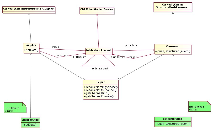
Figure 3.6: Event and Notification System
3.6.4.1An ACS API provides a simplified client and server API to connect to the
Notification Service and to create/connect/disconnect channels in the Event and Notification System. This does not hinder direct access to the CORBA Notification Service to access features not implemented by the API.
3.6.4.2 Note: The structured-push-supplier / structured-push-consumer model of the CORBA Notification Service has been implemented first. Other Notification Service models can be implemented later on based on specific application needs (Implementation not foreseen for ALMA).
3.6.4.3CORBA TCL (Trader Constraint Language) query language is used to allow filtering of messages from clients. Filtering is currently only allowed on simple CORBA types like Floats, Longs, etc.
3.6.4.4Notification Service servers can be federated to guarantee system redundancy and to provide higher reliability (Provided by CORBA but not integrated in ACS yet). Federated Notification Service servers allow:
- Load balancing. Client access can be split among different servers
- Security. Just specific servers, with a reduced set of published data (defined using filtering), can be allowed access from remote sites. This can be used to allow remote monitoring of ALMA from Europe and USA without exposing to the Internet confidential data.
3.6.5The Notification Service is a process separated both from publisher and subscriber. It also optimizes data transfer by implementing caching to reduce network traffic.
3.6.6The current ACS API provides a class for supplying events. An application instantiates a Supplier or Supplier-derived object and invokes the publishEvent() method that fills a CosNotification::StructuredEvent, which is the structure that defines the data sent on the Notification Channel. The Supplier class takes care of the whole administration of the Notification Channel including its creation.
3.6.7SimpleSupplier is a subclass of Supplier designed specifically for publishing events defined as IDL structures, the normal and most common situation. It provides the interface used to push IDL structs onto the notification channel, creates the channel (if it doesn't exist), and hides all CORBA from the developer.
3.6.8The current ACS API provides a base class for Consumer as well. An application implements a subclass of this for each Consumer and provides an implementation for the push_structured_event() method that has the purpose of pushing the data in the received CosNotification::StructuredEvent into appropriate member variables. The base class takes care of the whole administration of the connection to the Notification Channel.
3.6.9In Java, the Consumer class can directly resolve the event type using introspection and does not need to be subclassed in most cases. In C++ instead, a SimpleConsumer template subclass can be used to handle events in a generic manner by passing the event type as a template argument.
3.6.10 The Supplier and Consumer classes have a common engine that has been factorized in the Helper common base class. In particular the Helper class provides common information such as the "kind" of the Notification Channel as registered with the CORBA Naming Service.
3.6.11 The CORBA API for the Notify Service does not provide for retrieving the identifiers of the suppliers and consumers that have been registered with it. When an application with open subscriptions terminates without explicitly closing these connections, the subscriptions remain open within the Notify Service, retaining resources (threads and memory) uselessly. For ACS 8.0, the interface to the Notify Service will be changed to delegate the creation of suppliers and consumers to an ACS entity (typically, Container Services), so that ACS can clean up connections left open when an application terminates.
3.6.12 ACS itself uses the Event and Notification System to provide basic services like logging and archiving.
3.6.13 Comparison between Event and Notification System, Direct Value Retrieval and Data Retrieval by Event:
3.6.13.1 The 3 data access mechanisms provided by ACS have different characteristics and are meant to be used in different situations.
- With the Event and Notification System, data subscriber and data publisher are completely de-coupled.
- With Direct Value Retrieval, the client needs the reference to the servant object to call get() methods that directly return the requested value
- With Value Retrieval by Event, the client establishes a callback-based direct communication with the servant that asynchronously delivers data to the client in a point-to-point communication scheme.
3.6.13.2 The Event and Notification System pattern is convenient when:
- the client is interested in receiving events of a certain type (for instance event logs, monitor point values or alarm events) and handling them regardless of their source. Since the potential number of sources is very large, it becomes very inefficient if the client must establish a connection to each potential source. In this case a Notification Channel is necessary as the mediator between publishers and subscribers. Publishers push data in the channel while the channel efficiently multicasts events to all subscribers that are interested in receiving them.
- many clients (in particular remote clients) are interested in the same data. With a point-to-point communication, the data producer would have to deliver data to each of many clients, with a potentially heavy impact on servant performances. With the Event and Notification System pattern, the servant pushes the data only once on the channel that will efficiently multicast the events to the interested clients allowing to keep constant the load on the servant.
3.6.13.3 Direct Value Retrieval and Value Retrieval by Event are convenient when the client needs to be in control of the rate by which it receives data from the servant (asking directly for the values, when required, or establishing monitors with a specific data rate or triggering condition.
3.7Error System
The Error System provides the basic mechanism for applications to handle internal errors and to propagate from server to client information related to the failure of a request. An error can be notified to the final user and appear in a GUI window if an action initiated by the user fails (for example a command activated from a GUI fails).
3.7.1The architecture of the ACS Error System is based on the architecture and design patterns described in details in
[RD44 - ARCUS Error Handling for Business Information Systems ]
.
3.7.2 The Error System propagates error messages making use of OO technology. The basic error reporting mechanism is to throw an exception.
3.7.3The error reporting procedure must be the same regardless of whether the communication is intra-process (local) or inter-process (remote), synchronous or asynchronous.
3.7.4Errors can be propagated through the call chain as an ACS Exception or an ACS Completion to be reported to the action requester
[RD01 - 6.3.6 Scope]
.
3.7.5An ACS Completion is used to report both successful and unsuccessful completion of asynchronous calls. More in general, ACS Completions are used as return value or out-parameter in any case where it is not possible/meaningful to throw an ACS Exception.
3.7.6 The ACS Error System provides a mean to chain consecutive error conditions into
a linked list of error objects. This linked list is also called an Error Trace
[RD01 - 6.3.2 Tracing]
. It is not required that all levels add an entry in the trace, but only the ones that provide useful information.
3.7.7Both ACS Exceptions and ACS Completion contain an Error Trace. The Completion can contain no Error Trace in case of successful completion.
3.7.8Representation (see class diagram for details):
3.7.8.1ACS Error Trace is represented as a recursive CORBA structure, i.e. as a structure that contains information about the error and a reference to another structure of the same type (the previous Error Trace), to build the linked list. The Error Trace contains all information necessary to describe the error and identify uniquely the place where it occurred. In particular it contains an error message and context specific information as list of (name, value) pairs. For example, in the typical case of impossibility of opening a file:
- the error message would be: "File not found"
- the context information would be: ("filename", "<name of non existing file>")
3.7.8.2ACS Exceptions are represented as CORBA Exceptions and contain an Error Trace member
3.7.8.3ACS Completion is represented as a CORBA structure and contain an Error Trace member, that can be NULL in case of successful completion
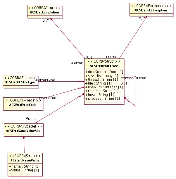
Figure 3.7: Error System data entities
3.7.9Inside a process, an ErrorTrace, ACSException and Completion are typically encapsulated into an instance of a Helper class, in the native language used for the implementation of the process (C++, Java and Python helper classes are provided directly by the ACS Error System). This class implements all operations necessary to manipulate respectively Error Trace and ACSException and a Completion CORBA structure.
3.7.10 For inter-process CORBA communication, the ACSException and Completion Helper classes transparently serialize the corresponding CORBA structure and transfer it to the calling process
[RD01 - 6.3.1 Definition]
. There it is deserialized into a new Helper class, if available.
3.7.11 Using this approach only CORBA Structures are transferred between servants and clients and it is not necessary to use Object by Value to transfer a full-fletched object. For languages where a Helper class is available, the encapsulation of the Error Trace structure into the Helper is equivalent to the use of Object by Value. On the other hand, languages where no Helper class is available can still manipulate directly the Error Trace structure. Also, Object by Value support from the ORB is not required.
3.7.12 In a distributed and concurrent environment, an error condition is propagated as an Error Trace over a series of processes until it reaches a client application, which either fixes the problem or logs it. At any level it is possible to:
3.7.12.1 Fully recover the error. The Error Trace is destroyed and no trace remains in the system.
3.7.12.2 Close the Error Trace, logging the whole Trace in the Logging System and then destroying the Error Trace. The error could not be recovered at the higher level responsible for handling it and it goes in the log of anomalous conditions for operator notification and later analysis. This typically happens for unrecoverable errors or when an error has to be recorded for maintenance/debugging purposes. This option is used also to log errors that have been recovered but that we want to record in the log system, for example to perform statistical analysis on the occurrence of certain recoverable anomalous conditions.
3.7.12.3 Propagate the error to the higher level, adding local context-specific details to the Error Trace (including object and line of code where the error occurred). The higher level gets delegated the responsibility of handling the error condition. This strategy implies that we might lose important error logs if the higher level application does not or cannot fulfill its own obligation to log error messages (for example because it crashes). It is therefore allowed at any time to log an important error trace (typically at debug level) as a precautionary measure to make sure it does not get lost. Logging it at Debug level ensures that the redundant information is not visible unless we are looking at logs in debug mode.
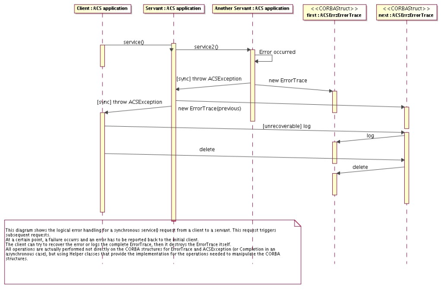
Figure 3.8: propagation of Error Trace
3.7.13 Error Trace, Completion and Exception Helper classes offer operations for
3.7.13.1 handling the addition of new error levels to the Error Trace while an instance is passed from one application layer to the higher one or from a servant to its client.
3.7.13.2 converting to/from Error Trace, Completion and Exception
3.7.13.3 navigating the elements of the Error Trace, i.e. querying for a specific error in the chain or for error details
3.7.14 Each Completion and Error Trace are identified uniquely by a pair
(Completion/Error Type, Error Code). If a Completion contains an Error Trace, it represents and error and therefore its Completion Type is the same as the Error Type of the top level Error Trace structure.
3.7.15 Error and Completion specification is done through XML specification files.
- The XML specification files allow defining context value pairs.
- Code generation is used generate type safe helper classes in all supported languages from the XML specification files.
- Getters and setters are generated for all context value pairs.
Each (Completion/Error Type, Error Code) pair is associated in the XML specification files to documentation providing help description of the error and of the recovery procedures to be taken
[RD01 - 6.3.5 Configuration]
.
- Help handling is implemented as links to XML help pages.
3.7.16 The Error System provides an API to access error documentation. (Not implemented yet)
3.7.17 An Error Editor GUI tool is used by application developers defining new (Completion/Error Type, Error Code) pairs and to manage them (insert, delete, edit the description) without having to edit by hand XML specification files. The tool ensures that (Completion/Error Type, Error Code) pairs are unique in the system and generates one XML specification file for each Completion/Error Type. (Partially implemented)
3.7.18 User interface tools allow navigating through the error logs and through the levels of the Error Trace
[RD01 - 6.3.4 Presentation]
. The logging display GUI is used to browse errors and a specific Error display tools is used to browse the Error Trace corresponding to a single error. (Partially implemented)
3.7.19 Errors have a severity attribute
[RD01 - 6.3.3 Severity]
3.7.20 It is important to take into account that exceptions can skip several layers in the call tree if there is no adequate catch clause. In this case the error stack will not have a complete trace of the call stack.
3.7.21 Particular attention must go into properly declaring exceptions in the signature of methods and in catching them; in C+, specifying exceptions in the signature of a method which then throws an exception not included in that specification can cause the process to abort at run time. The alternative approach, i.e., not specifying any exceptions at all in the signature, cannot be used for CORBA methods. Therefore the ACS error system documentation contains guidelines to follow in implementing proper and safe error/exception handling, in particular in C+.
3.8Logging System
Logging is a general mechanism used to store any kind of status and diagnostic information in an archive, so that it is possible to retrieve and analyze it at a later time.
3.8.1ACS Logging System is based on CORBA Telecom Log Service
[RD14]
and on the ACS Event and Notification System architecture
3.8.2Applications can log information at run time according to specific formats in order to record
[RD01 - 6.2.1 Logging]
:
- The execution of actions
- The status of the system
- Anomalous conditions
3.8.3 Logging includes for example:
- Device commands - reception and execution of commands from devices
[RD01 - 14.1.1 Logging of commands]
- Debugging - Optional debugging messages, like notification of entering/leaving specific code sections.
- Unrecoverable programmatic errors
- Alarms - change of status in alarm points
- Miscellaneous log messages. Applications can log events regarded as important to archive, for example receivers changing frequency, antennas set to new targets etc.
3.8.4Each log consists of an XML string with timestamp
[RD01 - 6.2.1 Logging]
,
information on the object sending the log and its location in the system, a formatted log message. Context specific information is entered as (name, value) pairs. The XML format is defined in the Log Markup Language (logMl) XML Schema.
3.8.5High level logs (for example logs directed to operators) are "type safe logs" defined in XML files, in a way analogous to error code specifications.
- The XML specification files allow to define context value pairs.
- Code generation is used generate type safe helper classes in all supported languages from the XML specification files.
- Getters and setters are generated for all context value pairs.
Each type safe log specification is associated in the XML specification files to documentation providing help description of the error and of the recovery procedures to be taken
[RD01 - 6.3.5 Configuration]
.
- Help handling is implemented as links to XML help pages.
3.8.6 Low level logs can be free format and are not required to be specified in XML type safe definitions.
3.8.7 The logging system is centralized so that eventually the logs are archived in a central log.
3.8.8Log clients can subscribe to the Log Notification Channel. The permanent Log Archive
[RD01 - 6.2.2 Persistency]
(an RDBMS) is essentially such a client and its implementation is left to the application.
3.8.9Applications log data using the API provided by ACS. This API provides methods for logging information of the different kinds specified above. A C++, Java and Python APIs are provided. The APIs are based on the standard logging facilities provided by the implementation language, when available:
- the C++ API is based on the ACE Log
- the Java API is based on the J2SE Java Logging
- the Python API uses a generic ACS CORBA Logging service
3.8.10 Logs can be cached locally on the machine where they are generated by a logging proxy and transmitted to the central log on demand or when the local buffer reaches a predefined size. High priority logs are not cached but are transmitted to the central log immediately. The main purpose of caching is to reduce network traffic.

Figure 3.9: Logging System
3.8.11 In particular the C++ API is optimized for performance and reduced network traffic and implements caching.
3.8.12 In ACS, logs are directly generated in XML format on the publishing side and transported as XML strings inside the logging service. During the ACS 7.x development cycle, we experimented with a binary transport based on IDL structures, hoping that this would improve performance. To our surprise, however, we discovered that the CORBA-encoded structures occupied 3 times as much space as their XML counterparts, and that this produced performance degradations of a factor of 3 in C++ and 15 in Java. Needless to say, this avenue is now closed.
3.8.13 The log API allows for filtering based on the log level, so that log entries with low priority do not get logged. The filter can for example be set to log or not log debug messages. The filter level is determined at run time and can be set through a command or through external configuration files. This filtering is done at the level of the container, so that only log messages that pass the filter are sent out over the network.
3.8.14 The API includes support classes (logging guards) to prevent message flooding. It allows the application developers to control the logging of repeated error messages. We have decided NOT to implement an automatic mechanism capable of detecting whether the same message is being logged at too high a rate, because we think that a reliable implementation is very difficult to achieve and would in any case heavily impact performance. But this means that careless developers can flood the system with logs. We will have to assess later whether to implement a more sophisticated mechanism.
3.8.15 A generic CORBA ACS Logging Service is available for any CORBA application to log even if no specific API is available. The IDL interface of the CORBA ACS Logging Service provides, on top of the standard CORBA Telecom Logging Service, methods for each type of log defined in ACS. Values for the relevant log fields are passed as parameters and the Service takes the responsibility of formatting them in appropriate transport structures and sending them to the CORBA Telecom Logging.
3.8.16 A user interface (logging GUI client) allows to monitor the logs while they are produced, in quasi-real-time, and to browse the historical database off-line. It provides filtering and sorting capabilities
[RD01 - 6.2.3 Filtering]
. It provides searching capabilities. It is useful to filter logs by inclusion and exclusion and logical combinations based on any logging field, like:
- time
- process that generated the log
- name of item logged
- all things from a device node down to the leaves
- type of item logged
3.8.17 The log monitor is implemented as a Java application and it uses the ALMA Archive interfaces for accessing the historical logs in the ALMA Archive.
3.8.18 If the Logging System crashes or cannot keep up with log requests, subsystem performance should not be affected but the log system should record that logs have been lost. The log system will run with lower priority than normal application processes, in particular on the control system.
3.8.19 The logging system is NOT meant to allow "re-run" observing sequences from log messages, but to allow analyzing a posteriori the exact behavior of the system. Since the system will never be the same twice, it will never be possible
to execute twice exactly the same set of actions. The task of making observing sequences reproducible must be assigned to the higher level observation scheduler and the logging system has to be used to understand what eventually did not go as planned in the observing sequence and to fix the identified problems.
3.8.20 Debugging logs are always present in code. Multi-level output of debugging logs can be switched on/off by setting the priority for log filtering. No compile time debugging flags are necessary, except when strict real time concerns apply.
3.9Time System
3.9.1ALMA has a distributed HW pulse, with a 48 ms interval, that the hardware will synchronize to
[RD01 - 8.1.3. Distributed timing]
[RD30]
. Also devices on the CAN bus will be connected to the time bus to allow synchronization.
3.9.2All time data in ACS (APIs, timestamps….) is based on the array time
[RD01 - 8.1.1. Standard]
. We assume that non-Real-Time boxes are simply synchronized to the array time using standard protocols, like NTP.
3.9.3The Time System provides basic service for time handling. It includes:
3.9.3.1Abstract API to access time information in ISO format
[RD01 - 8.1.2. API]
and to perform time conversion, arithmetic and formatting
[RD01 - 5.3.1.
Time conversion] to/from various time systems (UTC, TAI…).
3.9.3.2 An abstract API for synchronization between applications based on array time.
3.9.3.3Timer classes to trigger events based on time
[RD01 - 8.1.4 Services]
:
3.9.3.3.1 Applications can create instances of the timer class and register callbacks to be executed when the timer event is triggered
3.9.3.3.2 Timers can be periodic (retriggerable) or oneshot events
3.9.4Absolute Time is internally represented in 100 ns since 1582-10-15 00:00:00, based on the OMG Time Service Specification. An IDL typedef is used to define the Time type:
- typedef unsigned long long Time;
3.9.5A TimeInterval is defined as the difference between two absolute time points:
- typedef long long TimeInterval;
3.9.6ISO format will be used "internally" whenever a string representation of time is needed. At User Interface level, more formats might be required. We provide now only ISO format. Users can request more formats via the Change Request SPR mechanism.
3.10 ACS Container
3.10.1 The ACS Container package is responsible for the implementation of the Container part of the Container-Component model of ACS. This includes design patterns and high level services to manage the life cycle of Components and Containers themselves
[RD01 - 5.1.2. Procedures]
. This high level management part is implemented in a specific sub-package called the Management and Access Control package.
3.10.2 Containers are supervised and managed by an ACS Manager. Manager and Containers cooperate to provide the following functionality:
- Instantiation and de-instantiation of Components.
Instances of Components are created when needed or when requested and destroyed when not needed any more.
- System startup and shutdown.
At system startup all needed Components are created and initialized in the proper order.
- Location of Components in the system.
A client does not need to know where a Component resides and objects can be relocated when necessary, for example to recover from failure, for testing purposes or for load balancing.
- Version control.
If a newer version of a Component is available, or if its configuration data changes, it must be possible to upgrade or reconfigure the service without interfering with its clients.
Different versions of the same Component can be loaded or relocated for testing purposes without requiring changes in clients.
- Administration control.
Administrative users must have an overview and control over the current state of the system, including existing services and clients, and must have the possibility to manually manage services. Administration functionality includes startup and shutdown of the whole ACS, Manager, Services and Containers.
3.10.3 Components will be registered in the CORBA Naming Service. Properties of Characteristic Components are not registered in the naming service, but are accessed by retrieving their CORBA references from the Characteristic Component that contains them.
3.10.4 Access to the CORBA Naming Service and Component's life cycle is handled by a Management and Access Control Interface. A Manager is the communication entry point for clients: it provides access to the CORBA Naming Service (with added security, see below) and delegates to Containers the task to manage the
life cycle (code loading, creation and destruction) of Components, based on the request of services from the clients.
3.10.5 The CORBA Naming Service is completely open and anybody can read and write into it. The Manager hides the CORBA NS and takes care of reading and writing into it under stricter control. A non-administrative client cannot get access to all information in the NS, but only to what the Manager provides. Should ACS fully implement the "authorization control" in the future, use of passwords and controlled access to the Manager could be used.
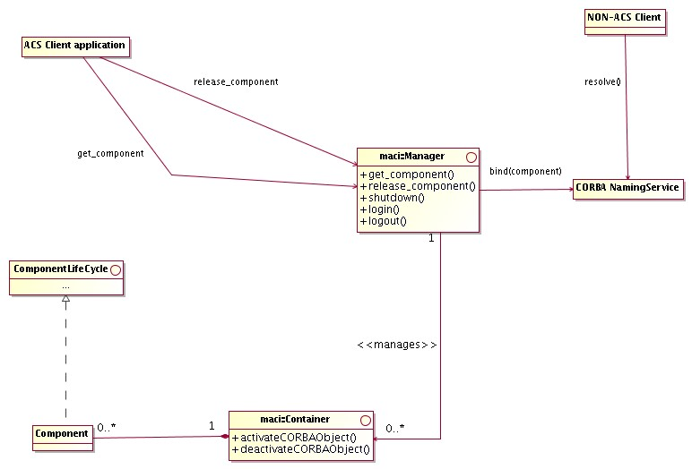
Figure 3.12: Management and Access Control architecture
3.10.6 The basic entities managed by the Management and Access Control interface (MACI) are Components.
3.10.6.1 To the management system, the Component is an entity with a lifecycle that has to be managed. Components can be instantiated in two different ways:
- regular Components are instantiated on demand when they are first requested.
- startup Components are instantiated when the system is brought online,
i.e. when the Container where they are supposed to live in is started.
3.10.6.2 A Component implements the functionality that allows the interaction between the MACI infrastructure and an underlying object. The underlying object can be a Java Component, a C++ Component or other type of objects, for example CORBA services, which have to be managed by MACI.
3.10.6.3 Every Component has a unique designation. Well-formed Component designations are Component URLs or CURLs. A CURL is a hierarchical name
implemented as a string of arbitrary length that consists of the static prefix curl:, domain identifier and Component name. An example of a CURL might be curl://alma/antenna1/mount, representing the mount Component for ALMA antenna number 1. MACI provides name resolution that from a well-formed Component designation generates the Component reference that can be returned to the client
3.10.6.4 Regular components are kept active if and only if there are clients referencing them. The Manager keeps track of all references and periodically verifies that the clients are still alive and deactivates unreferenced components.
3.10.6.5 The Manager provides an API to forcefully deactivate Components even if they are still referenced. This is used when shutting down parts of the system or when replacing at run time the implementation of a Component with anew one.
3.10.6.6 It is possible to have "non-sticky clients", whose reference to used components is not accounted by the Manager when deciding if a Component needs to be activated/deactivated. This is used, for example, for passive GUIs that monitor Components or interact with them only if the are already active for other reasons. Such "non-sticky clients" do not force the activation of a component if it is not already active when they request the reference from the Manager. In this way starting/stopping a GUI is unrelated with the status of Components and subsystems can be started up and shutdown independently from the GUIs.
3.10.6.7 It is possible to define a timeout before a regular Component not referenced any
more is deactivated. This is useful when there are multiple clients intermittently accessing a component for a long period of time and we do not want the server component to be all the time activated and deactivated. Notice that an "immortal Component", i.e. a component that is never deactivated after a first activation even is all clients release it, is essentially a component with infinite timeout for deactivation.
3.10.7 Manager is the central point of interaction between the Components and the clients requesting their services.
3.10.7.1 Manager has the following basic functionality:
- It is the communication entry point. A client requesting a Component service can do so by querying the Manager. Security is tied to this functionality by requiring every client to pass the authorization protocol and subsequently tag every request to the manager with a security token generated by the manager upon successful authentication. Manager serves also as a broker for objects that were activated outside of MACI (nonComponents). It provides a mechanism for binding and resolving references to such objects, relying on the CORBA naming service.
- It performs as a name service, resolving CURLs into object references. If a
CURL is passed that is outside the current Manager's domain, the Manager forwards the request to the Manager closest to the destination domain to resolve.
- It delegates the Component life cycle management to the Container objects and therefore creates no Components directly. However, it does maintain a list of all available Containers.
- The Manager uses the configuration database to retrieve relevant configuration for individual Components in the domain, as well as locations of other Managers.
3.10.7.2 Manager is the only interaction that clients have with MACI. Thus, neither Component implementers nor GUI client developers need concern themselves with aspects of MACI other than the Manager.
3.10.7.3 Manager implementation is based on CORBA Naming Service and all references to Components are available to clients not aware of MACI functionality through the CORBA Naming Service. A CURL-to-Naming Context mapping allows a one to one correspondence between Components retrieved using MACI services or from the Naming Service.
3.10.7.4 Manager provides also process control of Containers and CORBA services, i.e. it will be able to start/stop containers and CORBA services upon request.
3.10.7.5 A demon process runs on every host where Containers or services can be started. The Manager interacts with this demon to instruct it to start Containers. The demon provides also other services (in part still TBD) like collection of statistical data such as CPU , memory and disk load or availability (Partially implemented).
3.10.7.6 Manager can also deploy "collocated" Components, i.e. it can be requested to "deploy a Component in the same Container of another, given, Component"
- This allows applications to implement deployment recipes, for example for load balancing or for selecting the deployment configuration that satisfies specific application needs, without having to know explicitly the deployment of Containers or, more in general, the topology of the system.
- For example
- a pipeline application might deploy load balancing Components on all pipeline nodes at system configuration/
- a load balancing master Component can request information from load balancing Components (disk space, memory, load, performance characteristics....)
- based on this information can determine the best node where to run a specific pipeline stage Component
- it can then deploy the pipeline stage "collocated" with the selected load balancing Component
- this does not require to the application any explicit knowledge of the host and Container where the pipeline stage needs to be deployed.
- the load balancing Component need to be deployed at configuration time or using administration tools written for that specific purpose, but transparently to applications.
The Pipeline/Offline teams define the requirements for process management by the Manager and described above, like redistribution of processes/containers for load balancing, dynamic allocation of components to container or redundancy and replication of components.
3.10.8 A Container serves as an agent of MACI that is installed on every computer in the control system.
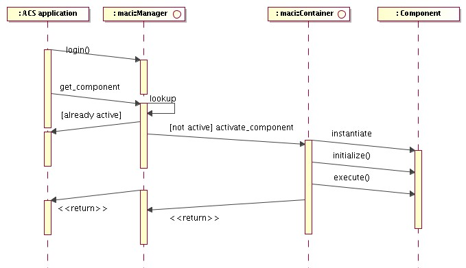
Figure 3.13: Component activation sequence
- Every Container runs in its own process.
- Manager sends the Container the request to construct/activate a specific Component by passing it the name, type and the path of executable code (depending on the implementation language) of the Component.
- The Container loads the executable code and begins executing it.
Depending on the implementation language, if the dependant executables are not loaded automatically by the operating system (as is the case on the VxWorks platform), Container loads them prior to executing any code.
- The Container also deactivates Components, when so instructed by the Manager and is able to shutdown by disabling all Components.
- Container maintains a list of all Components it has activated and is able to return information about an individual Component's implementation (such file path of the loaded code, version and build date).
- Container implements the ContainerServices interface to allow the Components it hosts to perform their MACI-related tasks, such as issuing requests to the Manager and activating other CORBA objects and to get hold of all the general services they may need.
Java, C++ and Python Containers will provide slightly different services, since the three languages are supposed to be used in different application domains.
It is expected that new services will be added to one or the other Container based on the application requests.
- The Java ContainerServices interface defines a number of services. Look at the documentation for more details. The most important are:
- Logger getLogger ()
Retrieves the logging system service object
- void assignUniqueEntityId (EntityT entity) throws
ContainerException
Get a Unique Entity Id assigned by the archive to entity data
- org.omg.CORBA.Object getComponent (String componentUrl) throws ContainerException
Retrieves e reference to another Component. This exists in a number of variants.
- void releaseComponent (String componentUrl) Releases another component
- DAL getCDB()
to access the Configuration Database.
- Object getTransparentXmlComponent (Class transparentXMLInterface, org.omg.CORBA.Object
componentReference, Class flatXmlInterface) throws
ContainerException
Converts a "flat-XML" component interface to a "transparentXML" component interface.
- The C++ ContainerServices is functionally equivalent to the Java one, but does not provide services equivalent to assignUniqueEntityId() and createXmlBindingWrapper(). The getLogger() method is provided directly by the Component base implementation classes and not through the ContainerServices.
- The Python ContainerServices is functionally equivalent to the Java one, but does not provide services equivalent to assignUniqueEntityId() and createXmlBindingWrapper().
3.10.9 There can be two types of Containers:
- Porous Container
- Porous Container returns to clients directly the CORBA reference to the managed Components. Once they have received the reference, clients will communicate directly with the Component itself and the Container will only be responsible for the lifecycle management and the general services the Container provides to Components, like Logging.
- Tight Container
- tight Container returns to clients a reference to an internally handled proxy to the managed Components. In this way the communication between client and Component is decoupled allowing us to implement transparently in the proxy layer extra security and optimization functionality, at the expense of an additional layer of indirection, with some performance implication.
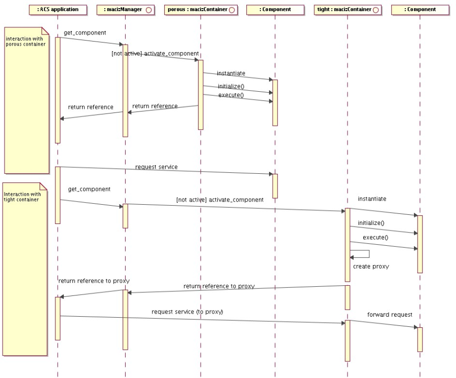
Figure 3.14: Porous vs. Tight Container access sequence
3.10.10 ACS provides just one implementation for the Manager interface (in Java) and three implementations for the Container:
- C++ Container
- C++ Container is a "porous" Container to allow better performance avoiding the extra level of indirection introduced by the tight Container wrapper. A C++ Component is assumed to be part of a Dynamically Loaded Library (DLL). Whenever the Manager requests a Component from a C++ Container, it passes the reference to the DLL to be loaded. The DLL is loaded dynamically and the Component instantiated and activated. When the Component is released, the DLL is unloaded.
- Java Container
- Java Container is a "tight" Container. The Java Class for a Component is dynamically loaded on request by the Container and unloaded when not needed any more. The "tight" implementation allows the transparent implementation of the (de)-serialization of entity (data) objects that appear in the parameter lists of operations. This functionality is very important for high-level Java applications. This means that a Java "binding class" which is a type-safe representation of XML data is transported across processes in the form of an XML string, even though the client and server component only see the real Java classes. This is also true for sequences of entity objects, or structures that contain entity objects.
There will be one JVM for each Java Container. In each Container we will have many Components, all running in the same JVM. This protects in a better way one Container from another and resource balancing is done redeploying Components from one Container to another in the same or in another host.
On the other hand, starting up and keeping alive JVMs is quite expensive. This is particularly important for user interfaces: a user can start at wish many GUIs on the same console, easily overloading the host. Therefore GUIs will have the capability of running inside the same JVM (when a new application/GUI is started, it looks for an existing JVM able to host it. This mechanism is implemented in ABeans 3. GUIs can be just clients for Components or they can be Components themselves.
- Python Container
- Python Container is a "porous" Container. A Python package for a Component is dynamically loaded on request by the Container and unloaded when not needed any more. Python is used to implement Component that have a strong requirement for flexible and easily editable procedures. Typical examples are pipeline and data reduction recipes. Such recipes are often edited by astronomers or by operators also during operation and are therefore better implemented using a scripting language; the Python components typically use and interact with C++ and or Java Components that implement CPU intensive algorithms, for example interfacing with Fortran legacy procedures..
3.10.11 Specialized Containers
- It is possible to create new Container implementations for specific application purposes.
- ACS Containers are implemented as classes that can be inherited from and extended. For example, specific initialization of legacy systems or data reduction packages to be used together with ACS components can be delegated to specialized containers
- specialized Containers can also be used to implement statically linked ACS executables. The Container will look from the Client and Manager point of view as a standard Container, but the libraries implementing Components are statically linked and instances of Components can be predefined in the linked executable. This was discussed for the implementation of the Offline Data Reduction Framework and ACS can, upon request, provide a standardized implementation for a few specialized containers.
- The Task (see Task section) is a specialized Container that can be run as an executable and does not require Manager or ACS services.
3.10.12 Every client of a Component service that is not itself a Component shall implement an interface called maci::Client.
- The Client interface allows the client to act as a secure party in the communication with the Components, to receive general-purpose string messages from the MACI components and to be notified when any change happens to the Components that the client utilizes.
- The log in and other requests are issued to the Manager, which serves as a portal to other services.
- Each Client logs in to the MACI system before any other requests are made, and in turn it obtains a security token, which it must use in every subsequent request to the MACI (Partially implemented).
- The authentication can be implemented using a plugin design. If the Archive User Repository is available and if desired, the corresponding plugin will allow to authenticate clients based on the User Repository (Implementation not foreseen for ALMA).
- maci::Administrator is a special-purpose client that can monitor the functioning of the domain that it administers. Monitoring includes obtaining the status of the Components as well as notification about the availability of Components.
- MACI allows organizing Components hierarchically and handling startup and shutdown dependencies between objects.
- Whenever a client needs a CORBA reference for a Component, a request to Manager is done for the corresponding Component.
- If the object is not already instantiated, the Manager asks the Container to create it.
- When an object contains hierarchical references to contained objects, the dependency is expressed via Component URLs and resolved through requests to the Manager. In this way, the Manager can automatically achieve instantiation of not already active nested objects. This guaranties that all objects are automatically created in the right order and when needed.
- Some objects are needed immediately at bootstrap. They are directly specified in a Manager configuration table (stored in the Configuration Database) and the Manager instantiates them as soon as the Container responsible for their deployment is bootstrapped.
- If there is a root top-level object, just putting this object in the Manager table will trigger a cascade instantiation of all dependent objects.
3.10.15 The Manager is the only responsible for providing references to Components.
- It is not allowed to directly pass a CORBA reference to a Component from one Component (or more in general, client) to another.
- Whenever a Client needs to access a Component, it shall request the reference by name from the Manager, by using the service calls provided by the ContainerServices, or by using directly the Manager's IDL interfaces
- If a Client needs to pass to another client information about a Component to be accessed, this shall be done by passing the Component's name. The Client will then have to get the component reference from the Manager using this name.
- In exceptional situations, Components need to instantiate objects that are accessible remotely, and need to pass them around to other Clients. The ACS::OffShoot interface is a base interface defined for this purpose. ACS::OffShoot objects are instantiated by a Component, who is responsible for their whole lifecycle. Their lifetime is limited to the lifetime of the Component who created and handed them over to clients. Mostly ACS:OffShoots are used internally by ACS, for examples ACS:Callback and ACS:Monitor objects.
- This is because the Manager needs to keep directly track of all the ClientComponent associations to be able to handle failures and restarts of Components and to allow administrator Clients to get a realistic picture of the status of the system.
3.10.16 An Object Explorer User Interface tool is provided to navigate the hierarchy of Components on the naming hierarchy.
[RD01 - 5.1.3 Browser]
- The Object Explorer is equivalent and covers the requirements of the
Device Browser Tool described in the
[RD45 - EVLA Engineering Software Requirements, 1.1 Accessing a Single Device]
.
In order to cover all detailed requirements expressed in [RD45], extensions to the Object Explored will need to be implemented.
- All objects in the system can be reached by navigating the hierarchy and all object information can be retrieved and edited, including accessibility
for a given user . For example, it is possible to graphically browse the hierarchy of Components in the system, based on the naming hierarchy, reach every single Component and view/edit all values of Properties and Characteristics.
The Object Explorer allows to browse the interface
[RD45 - 1.1-R4]
and send any command supported by a Component
[RD45 - 1.1-R5]
It is possible to monitor and draw trend-plots for each property
[RD45 -
1.1-R3]
- The Object Explorer uses the CORBA Interface Repository to retrieve information on the interfaces provided by the Components in the system.
Requirements in
[RD45 - 1.1]
not covered by the current Object Explorer implementation are:
- 1.1-R2 - Tabular representation of multiple monitor points
- 1.1-R3 - Plot multiple monitor points on the same plot (this is possible with the ACS Sampling System)
- 1.1-R5.4 - Send a command repetitively
- 1.1-R5.5, 5.7- Save, read and execute sets of commands from file
- 1.1-R8 - Save tabular data with monitor values (this is possible with the ACS Sampling System)
- 1.3 Accessing Multiple Devices
3.10.17 An Administrator User Interface (ACS Command Center) tool is provided. The Command Center:
- allows to start/stop ACS Services, Manager, Containers and Components on the local system or remotely
- displays the information about objects in the system. This includes Components, Managers and Containers. Both currently active Components and potentially active Components (i.e. Components that the Manager is able to bring online on request) are displayed.
- interacts with the Manager through IDL maci::Administrator interface, by receiving notifications about other clients and activators in the system from the Manager.
- acts as a central user interface for starting up administration utilities (logging client, object explorer, event monitor and others), providing a configurable menu structure.
- makes available to developers an API and GUI elements to implement administration applications and GUI.
The ALMA Executive is an application based on this API and GUI building blocks.
3.11 Daemons
All ACS services and containers described in the previous chapters can be started and stopped by executing scripts provided by ACS. To execute these scripts directly, the user must be logged in on the host machine, or use the remote-ssh features provided by the ACS commandcenter or the Alma Operator Master Client. Running ACS scripts in this way is still recommended for development and modular testing, but any large scale testing or real operations of the system should start ACS services and containers in a different way, using the ACS daemons.
There are two types of daemons, one for managing ACS services, and one for managing ACS containers. They must be started before ACS, where "ACS" now refers to the services and containers only, excluding the daemons which of course are also part of ACS in terms of software development and packaging. The starting can be done as part of the host machine's boot sequence, or later using some initialization framework outside of ACS. The ACS daemons are implemented as Corba aware application, that are not daemons in the sense of the operating system.
An ACS daemon only manages ACS services / containers on its local host machine, which means that a daemon must be running on every machine that should run ACS services and/or containers. There is at most one instance per daemon type running, handling all ACS instances ($ACS_INSTANCE numbers).
By default an ACS daemon can only be shut down by killing the process, which ensures protection if a privileged user account is used to start the daemon. As of ACS 8.0.0, it is not yet possible to have ACS services or containers started as a different OS user than the one who started the daemon; this feature may have to be added in the future.
The daemons will monitor their services or containers, and will raise alarms and/or restart the service in case of failures.
3.11.1 Services daemon
- A services daemon can start, monitor, and stop one or more of the ACS services.
- Services can be run on different machines, in any combination, e.g. CDB and manager on one machine, the Log service on another, and so on
- The daemons offer two APIs:
- A "direct" API that lets the client decide what services to start in which order. The client must connect to the daemons on all machines it wants to use. The daemon does not check the order in which services are started, nor illegal attempts to start a singleton service twice.
- A more sophisticated API that builds up or takes an existing XML based services description, and then processes it. Here the daemon knows about service dependencies and will start services in correct order. The client can connect to the services daemon on an arbitrarily selected machine, and send the service requests for all machines; the daemon will contact other daemons as needed.
- Internally the services daemon consists of separate processes:
- One main process that is the contact point for the daemon clients
- Per type of service it runs one "Imp" process to which it delegates the actual work. For example, if a client requests to run the Corba naming service, the CDB, and 5 different Notify Services on a host machine, then a total of 3 Imps get created.
- This design makes the daemon more robust, as the Imps can be restarted transparently. It also allows for specialized Imps, e.g. an Imp for running the ACS manager, which is itself written in Java in order to probe the manager's threading situation over JMX calls.
- The services daemon is started with the command acsservicesdaemon. When started with the --unprotected option, the services daemon can be shut down using the command acsservicesdaemonStop. This is mostly useful when using daemons as part of automated tests, that clean up after themselves.
3.11.2 Container daemon
- A container daemon can start and stop a container.
- In the future it should also monitor containers.
- A container daemon is required to be running if an ACS container is configured in the CDB to be started automatically by the manager (at ACS start, or upon direct request to a component that should run in that container, or upon indirect request by an autostart component configured to run in that container).
3.12 Parameters
3.12.1 ACS provides support for parameter sets.
- In general terms, a parameter set is a group of related parameters (i.e.
variables) with some additional metadata describing various aspects of the parameters.
- The parameter set mechanism was designed specifically to address the needs of the Offline team in the realm of Offline tasks, wherein data processing or reduction tasks will be defined (by a task author) by formally describing the input/output parameters (output parameters not yet implemented), plus some additional metadata such as help information, valid ranges, default values, whether the parameters are required or optional, etc.
- While the parameter set implementation was developed specifically with the Offline team's needs in mind, it is general enough in design that it may prove useful in other contexts; any application that needs to define and use sets of parameters (described in XML), with the parameter set instances parsed and validated against constraints (defined in metadata) may find it useful.
3.12.2 XML has been chosen as the description language for both parameter set metadata and parameter set instance data.
- Parameter set meta-data includes things like which parameters in a parameter set are optional vs. which are required, default values for parameters, help information, valid ranges (e.g. max, min, etc.), and additional information which does not describe the actual data for a particular instance of the parameter set.
- The parameter set (instance) data is a set of values describing a particular instance of a parameter set, with actual values defined for the parameters. For example, a simple parameter set metadata description might define 3 parameters: an optional integer X, a required double Y, and a required string Z, while the parameter set instance data for a particular "run" for this parameter set might be: X=1, Y=2.5, Z="vlafiller-output".
3.12.3 The following use cases are envisioned:
3.12.3.1 Parameter set metadata is defined in XML
The metadata is described in an XML file. The metadata for a parameter set includes defining the number and types of parameters, default values, validity constraints (e.g. max, min, ranges, etc.), help information, whether a parameter is optional or required, and other such pre-runtime information about parameters. The parameter set metadata is defined in a particular XML format with the schema (xsd file) provided by ACS. A simple text editor or an XML-savvy editor such as XML Spy can be used to create the metadata XML file.
3.12.3.2 Parameter set instance data is defined in XML
The instance data for a parameter set is a set of actual values for a particular "run" or "instance" of a parameter set. This is defined in XML with the schema (xsd file) provided by ACS. A simple text editor or an XML-savvy editor such as XML Spy may be used to create the parameter set instance data XML file. It is also envisioned that parameter set data files may be created programmatically in certain contexts, e.g. a graphical user interface may prompt a user for data, then construct the XML data file based on the user's responses.
3.12.3.3 Parameter set metadata and instance data XML are parsed and validated, building an in-memory object model
This use case is performed by the system automatically, by constructing two ACS-provided classes. The input necessary to construct the classes is simply to designate the parameter set metadata and instance data XML files to be used. A set of ACS classes have been written to take the XML files as input, parse them, validate them, spit out errors or warnings (if any), and finally - upon successful validation - create an in-memory object model of both the metadata and the instance data which can be manipulated and interrogated programmatically using a well-defined API.
3.12.3.4 Parameter set metadata and instance data object model are manipulated programmatically
ACS provides two classes (implemented only in C++) to represent the in-memory metadata and instance data for a parameter set. ParamSetDef is a class which represents the metadata for a parameter set. ParameterSet represents the instance data for a parameter set. Each of these classes has methods which may be useful for developers who need to manipulate a parameter set programmatically after it has been parsed and validated.
3.12.4 Architecture and design
The object model for the in-memory representation of a parameter set's metadata and instance data are depicted in the following three figures (more compact diagrams are available in the online mode, but it was impossible to have them
ALMA Common Software Page: 70 of 103
Architecture
printed in a readable way in this document). The API allows for querying the data in a relatively straightforward manner.
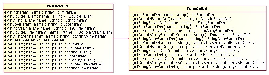
Figure 3.10: Parameter Set instance data (ParameterSet) and Parameter Set Metadata (ParamSetDef) classes
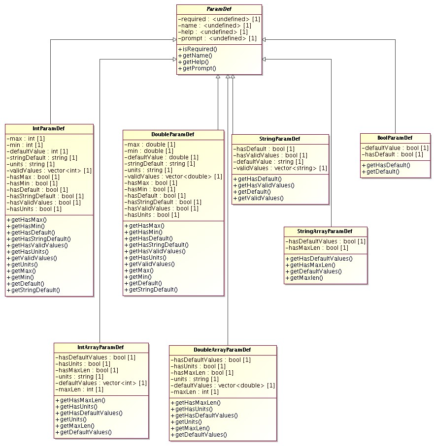
Figure 3.11-a: Parameter Metadata types. Subclasses of ParamDef used to build a ParamSetDef
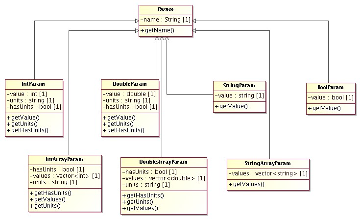
Figure 3.11-b: Parameter instance types. Subclasses of Param used to build a ParamSet
3.13 Tasks
3.13.1 ACS provides support for tasks.
- A task is a concise program which starts up, performs some processing, and then shuts down.
- A task may or may not require other more advanced ACS services, depending on context. Tasks are specifically intended to address the needs of the Offline team, which needs to be able to implement concise, standalone programs which perform some offline data processing or manipulation.
- It is expected that tasks will often be run from the Unix command prompt by typing a simple command (task name) plus some additional information describing the data to be used by the task.
- It is desirable, therefore, that a complete ACS startup scenario not be required in order to run a task; rather, the running of a task should simply involve typing a single command at the unix command prompt.
3.13.2 In order to facilitate the requirement of a simple execution mechanism (i.e. no complete ACS startup required), ACS provides a task mechanism that is able to run either with or without ACS services being up and running.
3.13.3 In addition, a special "static container" has been developed which allows the functionality for the ACS container to be linked in directly with the task executable at compile/link time.
- The static container functionality allows the Task mechanism to adhere fully to the ACS component-container model while still requiring no complete startup (e.g. no explicit starting of a C++ container is necessary).
- In the event that ACS services are available, the Task component, using the linked-in static container, will be capable of operating like a fullfledged ACS component.
3.13.4 Tasks will often require parameters (see Parameter section), so two primary types of tasks are provided.
3.13.4.1 A generic Task interface is provided which defines only a single method, run(), which must be implemented by the task developer.
3.13.4.2 A specialization of this generic Task is also provided, ParameterTask, which extends the basic task interface and allows for both a run() and a go() method.
In ParameterTask, the run() method is implemented by ACS and provides support for defining/parsing parameters passed in via the unix command line, converting the command line parameters to XML in order to construct a ParameterSet object, and then calling the go() method (which will be implemented by the task developer).
3.13.5 Architecture and design
The Task architecture is very straightforward.
Two IDL interfaces are defined by ACS: Task, the generic task base class, and a specialization of the Task base class which adds command-line parameter handling, ParameterTask.
Both of these types extend from ACSComponent, making them full-fledged Components in the ACS Component-Container model.
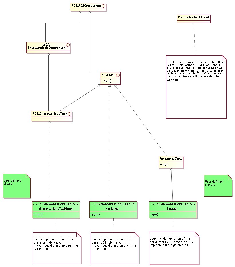
Figure 3.15: Task Component Architecture
3.14 Serialization
3.14.1 Entity data, i.e. complex data structures of moderate volume, are often represented as XML in the ALMA system. According to the ALMA Technical Architecture described in the ALMA Software Architecture
[RD33]
, XML is used to:
- define the content and structure of the entity objects that are passed between subsystems
- automatically generate the classes needed to access the data contained in these entity objects, optionally validating changes to a data value by an explicit call to validate() or implicit validation during (un-)marshalling;
- serialize these objects for network transmission;
- facilitate the storage of these.
3.14.2 The primary language used to define data entities in ALMA is UML, c.f. ALMA Software Architecture
[RD33]
.
3.14.2.1 UML is used as a higher-level layer, from which the previously hand-crafted XML Schemas are now automatically generated. The data transport format will remain XML though, and the XML schemas are still visible to developers when defining database queries.
3.14.2.2 Support for data modeling, code generation, and data handling in ALMA is split between ACS and the HLA subsystem:
- ACS provides the generator framework,
- HLA maintains the UML model and defines what code gets generated from it
- ACS provides generic mechanisms to generate Java binding classes from XML schema, and to present instances of these classes to application software, thus removing the need to explicitly deal with XML data. See below on details.
3.14.2.3 We assume that access to entity data will be primarily of concern to Java high level applications, therefore ACS priority is to provide optimal support for Java.
3.14.3 Entity data structures are conceptually defined as UML classes. Technically they are defined by means of XML Schemas which are derived automatically from
UML.
3.14.4 Programming language classes (for example Java, C++ and Python) to wrap and facilitate access to entity structures could be generated automatically from the XML Schema (XML binding to language-specific classes). The Castor
[RD36]
open source framework is currently used for Java binding. Castor XML binding provides also validation code for the accessors, based on the XML Schema. A similar, but not as complete, open-source binding framework for Python, generateDS, will be delivered with ACS 8.0. No such facility is currently foreseen (or required) for C++.
3.14.5 For data structures defined in UML, code generators are based on the Open ArchitectureWare Project
[RD39]
generator framework. We generate from the XMI UML representation:
- XML Schema as described in the previous paragraphs
- Binding classes for Java (based on Castor), C++ and Python (custom made)
- IDL interface definition files
- HTML documentation
- any other format needed, by implementing custom generators
3.14.6 Entity data is passed among Components as XML strings
[RD01 - 10.5.10 XML]
. Each Component operation that sends/receives an entity data structure, will have an IDL interface where the corresponding parameter is represented as a CORBA string. This is a commonly accepted way of implementing serialization.
[RD01 - 3.3.2. Serialization]
and migration
[RD01 - 3.3.3. Migration]
of objects without using CORBA Object by Value (ObV). As already mentioned in the Error System section, ObV is not implemented by most ORBs, is still immature and its usage is problematic.
3.14.7 ACS Java Container makes (un)-marshalling transparent to the user, interposing a proxy class between the IDL stub/skeleton and the implementation:
- Given the IDL description of a Component, a code generator is used to generate a <Component>Interface class. In this class, every EntityDataXML parameter has been replaced by the corresponding EntityData binding class.
- Java introspection is used to dynamically generate a
<Component>DynamicProxy and a <Component>DynamicSkeleton class.
- <Component>DynamicProxy is used by clients and converts client side calls from the EntityDataXML to the EntityData (un)-marshalled calls and forwards the messages to the <Component>Stub class generated by the IDL compiler.
- <Component>DynamicSkeleton is a delegation class that converts servant side calls from the EntityDataXML to the EntityData (un)-marshalled calls and forwards the message to the user defined <Componet>Impl real implementation class.
- Clients and the servant implementation of the component will therefore only see the interface of the <Component>Interface class, that does not use XML strings but binding classes.
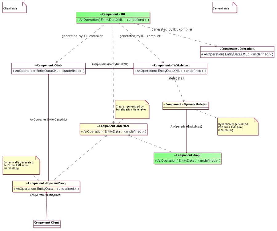
Figure 3.16: Example of class diagram showing transparent Entity Data serialization
3.14.8 The usage of the proxy approach allows the container to:
- Shortcut local calls (i.e. calls inside the same Container), so that no XML serialization is needed and the binding class is passed directly (not implemented yet).
- Intercept calls to Components, allowing the implementation of the Tight Container pattern (see ACS Container section).
3.14.9 For C++ and Python it is not foreseen to implement transparent (un-)marshalling like in Java. This choice is based on the assumption that Java clients and Components will be the most adequate whenever serialization is needed. If C++ and Python support will be necessary, they will be implemented at a later stage based on the code generation engine (Not implemented yet).
3.14.10 In case no XML binding generator is available (for example for clients written in a language different from Java, C++ or Python), we anyway expect that it will be acceptable to work directly on the XML strings with an XML parser.
3.15 Archiving System
3.15.1 The archiving system provides archiving of monitor point values. ACS provides only the data collection mechanism and not the storage of data. Data are made available from the archiving event channel.
3.15.2 The value of each Property of Characteristic Components can be archived. Archiving is enabled/disabled and configured on a per-Property basis.
3.15.3 ACS Properties publish their value on a specific ArchivingChannel notification channel, by using the ACS Logging System.
3.15.4 The parameters for data publishing are defined using the following Characteristics defined for all Properties:
archive_priority: The priority of the log entry that will carry the information required for archiving the parameter's value. If the priority exceeds the value specified in the MaxCachePriority, the archiving data will be transmitted immediately. If it is below MinCachePriority, the data will be ignored. If it is somewhere in-between, it will be cached locally until a sufficient amount of log entries is collected for transmission.
archive_max_int: The maximum amount of time allowed passing between two consecutive submissions to the channel. If the time exceeds the value specified here, the entry should be submitted even though the value of the parameter has not changed sufficiently. Publishing the value of the property at least once in a while allows to check that the property is really available and monitored.
archive_min_int: The minimum amount of time allowed passing between two consecutive submissions to the log. If the time is smaller than the value specified here, the value is not submitted, even though the value of the parameter has changed. Definining a minimum time interval allows to filter out quick oscillations and avoids flooding the system.
archive_delta (same type as parameter): Defines what change in parameter value is needed to trigger publishing the value. If the value changes for less than the amount specified here, no value is submitted. For Pattern and String properties, this Characteristic is irrelevant. That is, any change in the Property's value will trigger the Monitor.
3.15.5 Whenever the Characteristics of a Property are such that archive values have to be submitted, a BACI Monitor is created to periodically submit the values to the Logging System.
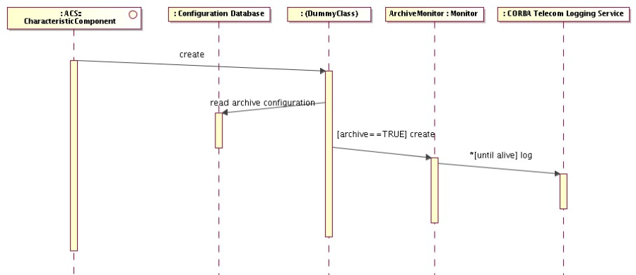
Figure 3.17: Archiving System sequence diagram
3.15.6 It is possible to switch archiving on/off using an API, to make sure that no values are published when the Property is in a state where values are not meaningful
For example, a Component might want to switch off archiving if it is not initialized, in an error state or disconnected form the hardware it is controlling.
3.15.7 The entries pushed into the ArchivingChannel are structured events with the following structure:
Name | Value | |
Event Header | domain_name | Archiving |
type_name | Type of parameter | |
Filterable data | time_stamp | Time when the parameter had this value, i.e. when the data for the log entry was sampled |
object | The object whose properties value is being reported | |
parameter | The name of the parameter within the object | |
value | The value of the parameter. The type of this field is the same as specified | |
in type_name. |
3.15.8 Clients can subscribe to the Archiving Notification Channel using filters to get events when archiving data is available. ACS provides an API that allows parsing the Notification Channel messages containing monitor point archiving data.
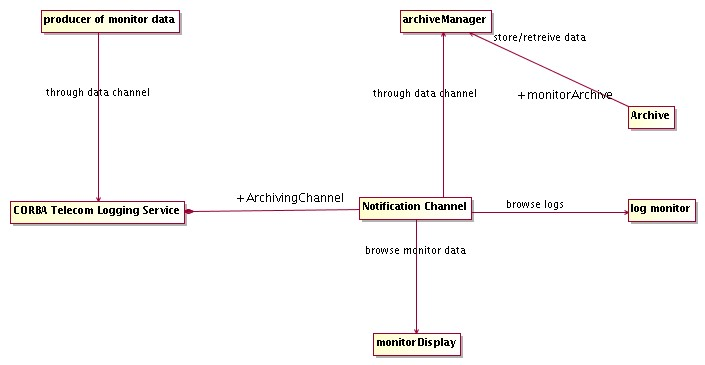
Figure 3.18: Archiving System architecture
3.15.9 Individual Properties data are cached locally before they are sent to the central archive
3.15.10 Each Property can be uniquely identified by a name, composed of the Characteristic Component name followed by the Property name.
3.15.11 The Archiving API can be used also to send to the archiving system data that does not fit in the Property design pattern.
3.15.12 Archiving of monitor point values is currently only supported in C++.
3.16 Command System
A command is the basic mechanism for communication from users to Distributed
Objects and between Distributed Objects. A command is actually a method of a Component.
3.16.1 Commands are sent to Components
[RD01 - 6.1.2. Commands]
using remote method invocation. It is based on CORBA
[RD01 - 10.4.1. CORBA] [RD01 - 13.1.1. Distributed Objects and Commands]
.
3.16.1.1 CORBA provides full support for inter-process communication.
3.16.1.2 CORBA objects have a public interface defined with the IDL language
[RD01 -
10.3.4. IDL]
3.16.1.3 CORBA objects can be remotely accessed by creating stubs and invoking the defined IDL interface.
3.16.1.4 Any language supported by CORBA can talk to any remote object, independently from implementation language and architecture. The Object Request Broker (ORB) does mapping of calls and marshalling.
3.16.1.5 CORBA defines a standard Internet Inter-ORB Protocol (IIOP) that guarantees interoperability between any CORBA implementation and vendor based on TCP/IP. Any implementation must comply with IIOP, but a vendor can choose to additionally implement high performance transport protocols. For example there are native ATM implementations. Same-process messages are usually implemented as direct function calls while same-CPU messages are based on operating system message queues.
3.16.1.6 Other non-IIOP CORBA messaging protocols, supported by the ORBs used in ACS, can be used to satisfy special communication and security requirements.
3.16.1.7 A call to a method of a CORBA Component, based on its IDL interface, is what can and has to be mapped into the concept of Commands (the method call concept is very similar to RPC).
3.16.2 A command has a well-defined syntax and set of call and return parameters. Full context validation and syntax check of commands is always done when the command is received by the server application
[RD01 - 6.1.4. Validation]
. A command can also be checked by the sender, but this is not mandatory except in the case of generic command-sending GUIs
[RD01 - 6.1.3. Syntax Check]
. The syntax check would check that the command is valid and that the parameters are within the static ranges.
3.16.3 Commands are synchronous (the caller blocks and waits for a return reply, up to a defined timeout)
[RD01 - 6.1.7. Mode]
[RD01 - 6.1.8. Timeout]
. Applications should take care of the fact that a synchronous call can block the whole application unless it is issued from a dedicated thread. Replies can be normal replies or error replies
[RD01 - 6.1.1. Messages]
.
3.16.4 CORBA Asynchronous Method Invocation (AMI)
[RD29]
can be used to implement asynchronous calls on the client side using synchronous methods on the servant side. AMI is only supported by a few ORBs, for example TAO and JacORB, but not by omniORB.
3.16.5 Asynchronous command handling using synchronous methods on the servant side can also be done by starting a separate thread, which sends a synchronous command. This way the main thread is not blocked.
3.16.6 Asynchronous command handling can also be implemented using callbacks, in particular when multiple replies need to be sent. ACS provides support for Callbacks and uses callbacks for Monitors.
3.16.7 Using synchronous commands, time-outs are handled using CORBA messaging (implemented in TAO but not in other ORBs)
[RD01 - 6.1.6 Command delivery]
. Intermediate replies are not handled by ACS, but must be taken care of by the application. ACS cannot therefore warranty that requirement
[RD01 - 6.1.9 Intermediate replies]
is satisfied. This is let to applications.
3.16.8 Commands can be invoked from generic applications, that are able to browse the objects in the systems, show the available commands with the corresponding syntax, check dynamically the syntax of commands and send them
[RD01 - 6.1.5. Programmatic use]
.
3.16.9 A server sub-system handling a command shall continue to operate if the client that has issued the command disappears, e.g. between a command being initiated and completed. In this case the server logs a non-critical error, since a wellbehaving client should always wait for replies to initiated actions, and continues.
3.16.10 Components publish their interfaces via IDL interfaces. IDL allows use of inheritance to build new types. IDL allows only defining the pure interface in terms of parameters and types; it does not allow specifying range checking for the parameters. This checking has to be performed by the applications. IDL interfaces are registered in the CORBA Interface Repository (IREP) and made public.
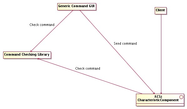
Figure 3.19: Command System architecture
3.16.11 The implementation of checking functions and tools to implement command syntax checking both at the sender and receiving side of commands is provided by the Parameter package and Parameters have to be used when command checking is necessary.
3.17 Alarm System
The Alarm System provides a mechanism for notifying asynchronously operators and registered applications of the occurrence of important anomalous conditions that can disrupt the observation or be potentially dangerous for the system
[RD01 - 6.4.1 Definition]
.
3.17.1 The design and implementation of the ACS Alarm System are based on the Laser system developed by CERN for the LHC accelerator
[RD19]
and take into account the OVRO hierarchical alarm system
[RD22] [RD01 - 6.4.5. Hierarchy]
. For more details on the Laser system and for a very good Alarm System Requirements Document see
[RD19]
.
3.17.2 An Alarm System API implemented in C++, Java and Python allows applications to publish Alarms.
3.17.3 Properties are able to trigger alarms. The simple alarm is triggered when the value
of the property exceeds or falls below the alarm limits defined for the property.
3.17.4 Hysteresis could be implemented for the alarm limits (Implementation not foreseen for ALMA).
3.17.5 Alarms are events published on an Alarm Notification Channel. Notification is done when the alarm is set and when it is cleared.
3.17.6 Whenever an alarm is set or cleared, the event is logged in the Logging System
[RD01 - 6.4.6. Alarm logging]
.
3.17.7 Alarm events are characterized by the following information:
- An enumerated state property with the values: GOOD, WARNING, BAD
- A timestamp property describing when the alarm status changed
A set of description characteristics
[RD01 - 6.4.7. Configuration]
, including (on top of the standard ones like description, URL for extended documentation...) a severity
[RD01 - 6.4.3. Severity]
3.17.8 An Alarm Server application keeps track of all active alarms.
3.17.9 Hierarchical alarms can be constructed by the Alarm Server that behaves as client on top of the available alarm system and re-publish hierarchical alarms.
3.17.10 The Alarm Server is also responsible to maintain State Alarms. These are alarms that maintain an internal state. In this case the alarm will be incarnated by an Alarm Object whose life cycle is controlled by the Alarm Server. They will have the following additional properties:
An enumerated occurrence property (FIRST OCCURRENCE, MULTIPLE OCCURRENCE....)
[RD01 - 6.4.4. State]
A property holding the status of user acknowledge, when required. Some alarms just disappear when the alarm condition is cleared, but others require an explicit acknowledgment from the operator
[RD01 - 6.4.2 Behavior]
3.17.11 It is possible to define actions that have to be started on the occurrence of a given alarm condition
[RD01 - 6.4.8. Binding]
. Applications can use normal Notification Channel techniques to request a notification to be sent for the occurrence of specific alarms.
3.17.12 An alarmDisplay GUI provides an operator user interface to the alarms. Using this application the operator can browse through the currently active alarms, request for detailed information and help about a specific alarm, acknowledge alarms when this is required.
3.17.13 The Alarm System supports the definition of reduction rules.
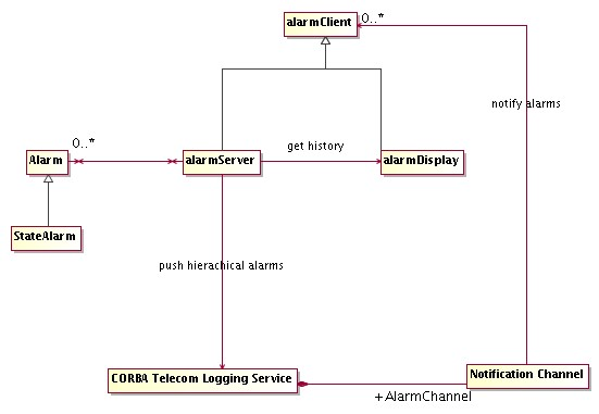
Figure 3.20: Alarm System architecture
3.18 Sampling
3.18.1 Every Property can be sampled at a specified sustained frequency, up to 200 Hz, limited by hardware.
3.18.2 A sampling frequency of 1KHz for a limited number of Distributed Object Properties must be allowed in order to implement a "virtual oscilloscope" whereby, for example, noise sources in the IF chains can be correlated and identified.
3.18.3 The Sampling System is equivalent and covers the requirements of the Fast Data Dump in
[RD45 - EVLA Engineering Software Requirements, 1.2 Fast Data Dump],
although it is not integrated in the Object Explorer.
3.18.4 The Event and Notification System transports sampling data.
3.18.5 The samples are stored in a data file for later analysis or to be passed to applications like MatLab for analysis of engineering data
[RD45 - 1.1-R8]
. Every sample is time-stamped to allow correlating data from different sources.
[RD01 - 4.3.1. Sampling]
3.18.6 The samples can be plotted in near real-time on a user interface on the operator terminal or any other user station. The plotting application subscribes to the sampling data from the notification channel, which is fed by the sampling manager, and periodically updates the running plot with the new data
[RD01 - 5.1.4 Analysis tool]
. The plotting application can also display sampling data from data files. The plotting application can be:
- A Java application that uses Java plotting widgets and in particular widgets aware of the Property internal structure to define plotting scales and units.
A COTS application, like LabView
[RD13]
[RD01 - 10.5.7 Analysis and plotting]
, with advanced plotting and analysis capabilities.
3.18.7 Multiple samples can be super-imposed on the same plot with the same time base, even if the data are received from different distributed objects, possibly on different antennae (Partially implemented). Also, it should be possible to plot samples against one another, an example being VI curves (voltage vs. current) used in biasing mixer junctions (Not implemented yet).
3.18.8 Data transport is optimized. The samples are NOT sent one by one to the central control computer responsible for storing data, but are cached on the local computer and sent in packets (for example with 1 Hz. Frequency). This is of primary importance to keep network load under control.
[RD01 - 4.3.1. Sampling]
3.18.9 There is a sampling engine implemented as a Component:
3.18.9.1 It can be activated on any local computer
3.18.9.2 Can be configured to sample one or more Properties at given frequencies.
3.18.9.3 It sends periodically at low frequency packets of data to a sampling server that stores the data for later analysis or provides them to near-real-time plotting applications.
3.18.9.4 Sampling must not reduce the performance of the control system or the network. The caching of data will reduce network traffic while assuring that the sampling processes runs with lower priority than control processes will reduce the impact on the performance of the control system.
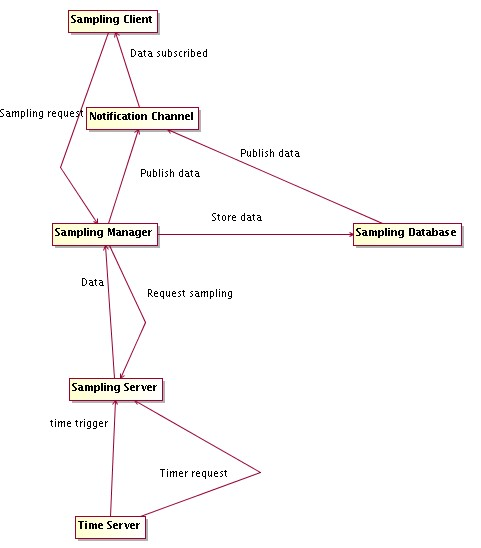
Figure 3.21: Sampling architecture
3.18.10 XML seems an interesting data format for sampling files. This format allows also easy data exchange with relational databases. Style sheets based on the eXtensible Style Language (XSL) can be used to transform XML files in other formats, like simple ACSII blank delimited tabular files.
3.19 Bulk Data
ACS provides support for the transport of bulk data
[RD01 - 7.1. Bulk data transfer]
, to be used for science data.
3.19.1 The following use cases are supported:
3.19.1.1 Push streaming. Connection initiated by the supplier.
A data supplier produces a continuous stream of data for a specific bulk data consumerComponent. Typical example is the Correlator sending continuous streams of data to the Archive.
The basic operations are as follows:
- The supplier gets access to the consumer Component
- Opens a connection.
- Data is sent by the supplier to the consumer until
- The supplier closes the connection
3.19.1.2 Push discrete bulk data. Connection initiated by the supplier
A data supplier produces bulks of data as separate, non continuous streaming, entities. Typical example is a data processing Component sending images to another Component for further processing. Everything works like in the previous case, but for the fact that the communication protocol must be able to identify separate bulks of data, like a single image.
3.19.1.3 Pull data from stream. Connection initiated by consumer.
An application needs streaming data published by a Stream Provider Component. There can be multiple clients. Typical example is a GUI connecting to a CCD camera. Multiple GUIs can display the image from the same Camera.
The basic operations are a follows:
- The supplier Component is available for publishing data
- The client opens a connection with the supplier
- The supplier sends data to the client(s) until
- The client closes the connection
3.19.1.4 Pull discrete bulk data. Connection initiated by the consumer.
An application needs to retrieve discrete bulks of data as separate, non continuous streaming, entities. Typical example is retrieval of images from the archive. Everything works like in the previous case, but for the fact that the communication protocol must be able to identify separate bulks of data, like a single image.
3.19.2 Performance considerations
It shall be possible to handle the actual transfer of data with communication protocols more efficient than CORBA IIOP, in particular for high volume streams.
When there are multiple clients for the data published we have implemented a service architecture in which the data supplier sends the data to just one Distributor which, in turn, sends them to a number of connecting clients. This decouples the load due to the increasing number of clients from the supplier.
Precise performance requirements have been collected and verified with the ACS Bulk Data system implementation based on the CORBA Audio Video streaming service. Tests have demonstrated that the ACS implementation can deliver 700 – 800 Mbit/s to three consumers simultaneously.
3.19.3 Architecture and design
3.19.3.1 Bulk data transfer can be implemented in CORBA using three techniques:
- Iterators on normal IDL methods
- Notification Channel
- Audio Video Streaming Service
The first two options are based on the IIOP transport protocol and therefore suffer from performance limitations, although tests available in the literature show that properly designed buffering limits these problems. Option 1 is better suited for discrete bulk data while option 2 is better suited for streaming.
Option 3 is based on the Audio Video Streaming Service
[RD42]
defined by CORBA. This specification aims at the streaming and transfer of large amounts of data and satisfies the requirements expressed in
[RD01 - 7.1.1 Image pipeline]
. The handshaking protocol is defined using CORBA IDL Media Control interfaces, but the actual data transfer goes out of band and does not use (but could use) CORBA to transport data. TAO provides an implementation and provides transport over TCP and UDP with excellent performance
[RD43]
.
3.19.3.2 The CORBA Audio Video Streaming Service supports all the use cases described above.
3.19.3.2.1 There are the following basic concepts:
- Stream
A stream represents continuous media transfer between two or more entities.
- Flow
A stream can be composed of many flows.
For example a video camera stream has a video and an audio flow. As an example strictly related to ALMA, the Correlator will have one stream to send bulk data to the Archive, but this would be split in up to 8 flows with at least 2 always present: 1 per subarray, 1 for spectral data and 1 for channel average.
Each flow can have independent quality of service parameters and each flow can have an independent direction (upload or download).
- Frames
A frame is a unit of data sent over a flow.
A frame of a video is a typical example.
A set of data published by the Correlator can be mapped to a frame as well.
The basic A/V service does not have the concept of frame. The SFP (Simple Flow Protocol), on top of the physical transport protocol, introduces the concept of frame in the A/V service and protocol messages to identify and number the frames are added to the actual data.
3.19.3.2.2 Data published on a Flow is received via a callback implemented by the receiving Component.
3.19.3.2.3 The push use cases are implemented using an upload flow. The pull use cases are implemented using a download flow.
3.19.3.2.4 The Bulk Data Components implement the Media Control interfaces (and extend them as needed).
3.19.3.2.5 Streaming use cases are implemented using the start control commands on the Component to notify that the stream has started and not sending the stop command until the stream needs to be closed. Structuring of the data sent in the stream or the SFP protocol are used for synchronization and framing of the message.
3.19.3.2.6 Discrete use cases are implemented using the start and stop stream commands to identify each discrete piece of bulk data. These will be wrapped in convenience interfaces. In this way it is not necessary to inspect the incoming data to identify the frame boundary and the end of data.
3.19.3.3 Limitations of the CORBA Audio Video Streaming Service
There is no implementation of CORBA A/V service for Java or Python. The producers and consumers of the bulk data stream (Correlator, Control, TelCal, Pipeline and Archive) all use C++ implementations of the bulk data senders and receivers as ACS components. Java and Python applications can access these components via the normal ACS/CORBA interfaces. There is therefore no requirement for implementation of CORBA A/V in languages other than C+. For example, image data processing typically takes place between C+
Components without requiring high performance image transfer to Java or Python Components.
3.20 User Interface Libraries and Tools
3.20.1 The Java language
[RD06]
is the current choice for GUI development, in particular coupled with the SWING graphical library
3.20.1.1 A rich set of widgets is part of the standard package.
3.20.1.2 Java is highly platform independent
[RD01 - 12.1.1 Portability]
. GUIs are platform independent and can be developed on any system and run on any other system
[RD01 - 12.1.2 Extended Portability]
.
3.20.1.3 Java Applets can run inside Web Browsers for the deployment of low complexity GUIs on remote sites
[RD01 - 12.1.2 Extended Portability]
.
3.20.1.4 Both Java and Web Browsers have good CORBA support. JacORB
[RD34]
is the ORB currently used to provide CORBA support in Java.
3.20.2 ACS provides in addition a standard set of tools for the development of user interfaces
[RD01 - 12.1.3 Tools]
. This includes:
3.20.2.1 Integrated Development Environment. A COTS Java Integrated Development
Environment, including a GUI builder, has to be selected. The current choice is Eclipse
[RD35]
, that is a multi-platform, free project, with the Eclipse Visual Editor project plugin. There is no point in developing a proprietary tool.
3.20.2.2 Standard set of widgets for the implementation of applications with common look and feel. The adoption of the Characteristic Component concepts allows reuse of many Java Beans developed in the particle accelerator community specifically for the implementation of control systems. In particular the ABeans developed for ANKA
[RD04]
provide a set of widgets for ACS aware of of the Characteristic Component design pattern. ABeans are integrated in Eclipse
[RD35]
as a plugin that makes use of the Eclipse Visual Editor. Performance problems with the Abeans implementation limit their usage to small GUI applications, with a limited number of widgets.
3.20.2.3 Standard Java class libraries for the integration with all services provided by the
ACS.
3.20.3 The ALMA Executive subsystem has designed a standard GUI user interface architecture that allows to implement GUI plugins for the main Executive GUI.
3.20.4 Plotting will be an important element in GUIs (see also
[RD45 - EVLA Engineering Software Requirements, 4 Plotting] [RD46 - EVLA Array Operations Software Requirments, 3.5 Plotting]
. ACS integrates an advanced
Java GUI class library
[RD47 - JFreeChart]
. Plotting widgets are integrated with ABeans for the development of applications and are available with all tools capable of monitoring values, like Object Explorer.
3.20.5 These Java and Python GUI tools allow developers and end-users to design and create their own display
[RD46 - EVLA Array Operations Software Requirments, 2.8 Display Builder]
.
3.20.6 All GUIs for generic ACS applications, (Object Explorer, logMonitor...) will be developed using ACS standard GUI libraries
[RD01 - 12.1.5 ACS GUIs]
. Tools, prototype and engineering GUIs can be implemented in Python.
3.20.7 GUIs shall not implement any control logic
[RD01 - 12.1.4 Modularity]
. They should be dummy applications that simply send commands to Components and access Properties of Characteristic Components for display and update. Any action performed through a GUI shall also be available using command line commands, script or simple programs and no GUI shall be strictly required to drive the system.
3.20.8 Online documentation and help
3.20.8.1 Integration with the Web through the usage of an HTML/XML Browser provides access to online documentation
[RD45 - EVLA Engineering Software
Requirements, 5 Documentation and Help] [RD46 - EVLA Array Operations Software Requirments, 1.4 Online Help]
.
3.20.8.2 Java help
Online help systems, for example for graphical user interfaces, shall use he the JavaHelp extension (http://java.sun.com/products/javahelp/index.jsp): help pages are written in html and they are rendered inside the application by the help browser that it pard of the Java Development Kit (jhall-2.0_02.jar). This allows to deploy help pages locally or throught the web and, the other way around, to reference and access web pages from the application's help browser.
- help location: an application passes the html resources to the help browser when it creates it. A webserver would be used if no help resources exists locally
- context sensitive help: GUI widgets providing context help shall be named using setName("abc") to allow identifying the proper help topic for them dynamically
3.20.8.3 Printed help and documentation
If the same document shall provide both online help and printed documentation, it is often convenient to write it in a higher level, more printing friendly, format than plain html, as long as a good conversion to PDF for printing and HTML for online usage are available and can be made automatic through Makefile.
3.20.8.4 A good and proven solution is Latex (currently used to produce OT documentation):
3.20.8.5 OT help pages are written in latex. Before each OT user test, Alan generates a pdf file from them which is good to download and printout.
- all help pages are kept together with the source code in the UserDoc directory
- the makefile take care of processing them to produce documentation:
- it runs latex2html
- it converts the postscript pictures to jpg
- it creates the meta-information needed for the Java Help Library (TOC, etc.) dynamically the rest is just the same as in the commandcenter
- packs them together in a jar file xxxHelp.jar
3.20.8.6 The Java Web Start
[RD40]
technology is used to deploy and update GUIs and more in general Java applications on remote sites without requiring installation of specific and heavy software packages. Using this technology, GUIs do not run inside the Web Browser but as stand-alone applications.
3.20.8.7 LabView
[RD13]
can be integrated with ACS and be used, for example, as a platform to develop engineering GUIs. It is possible to implement ACS
functions in LabView applications via Code Interface Nodes (CIN). In this way LabVIEW GUIs can control and interact with standard ACS Components.
3.21 Scripting support
3.21.1 Python
[RD24]
has been the chosen as the scripting language
[RD01 - 5.2.1 Scripts]
[RD01 - 10.5.6.Scripting language]
. Python, i.e. the C++ implementation, will be normally used. Special applications can use JPython (Java implementation).
3.21.2 It is used as a glue language between the high level interfaces and the control and data systems
[RD01 - 5.2.1 Scripts]
:
3.21.2.1 High level procedures of a coordination nature
3.21.2.2 System administration, replacing shell script languages for new developments
3.21.2.3 Rapid prototyping
3.21.2.4 Test applications and procedures
3.21.3 A Python Container supports the implementation of high level Components with a strong need for integrated scripting capabilities. Pipeline and data reduction recipes are typical examples. Such components will be used by higher level interfaces as coarse grained building blocks, easily modified and extended, that will in turn use lower level, fine grained C++ or Java Components.
3.21.4 Python provides access to the basic features of all Common Software services
[RD01 - 5.2.2.Functionality]
:
3.21.4.1 CORBA invocation of remote objects
3.21.4.2 A package of support classes implemented in the scripting language itself
3.21.5 Python
[RD24]
satisfies all requirements for the scripting language to be used in ALMA
[RD01 - 5.2.1 Scripts]
[RD01 - 10.5.6.Scripting language]
:
- Object Oriented
- Platform independent.
- Flow control, variables, and procedures.
- Plug and play to install scripting language.
- Connects to CORBA.
- Easy to use for non-programmers.
- Rapid Prototyping Similar to programming languages used in the project.
- GUI development.
- Embeddable into code for interactive applications.
3.22 IDL Simulator
Simulation
[RD01 - 3.3.4. Simulation]
is supported within ACS at the level of
Components. That is, ACS provides the necessary libraries for dynamically
implementing IDL interfaces derived from the ACSComponent IDL interface at run-time.
3.22.1 The simulator framework is available by specifying a special Python library as implementing the Component within the ACS Configuration Database
3.22.2 The behavior of simulated components can be configured "ahead of time" using the ACS Configuration Database in cases where a standardized behavior is desired
3.22.3 Complete implementations of all IDL methods and attributes can be implemented on the fly by the simulator framework
3.22.4 The behavior of simulated components can be configured at run-time using:
- a GUI which is spawned automatically with the creation of the first simulated Component
- the command-line and an easy-to-use API provided by ACS if the Python Container hosting the simulated Components was started within an interactive Python session
- the IDL interface provided by a Simulator Component. This Component shall be deployed in the Python Container where the simulated components are deployed.
3.22.5 Using any of these techniques it is possible to:
- replace or retrieve the code of each simulated method,
- set timeouts
- set/get the value of global variables
3.22.6 The framework provides realistic behavior of certain ACS types such as BACI properties and is capable of invoking Callbacks properly
3.22.7 The simulator includes the capability of creating other CORBA Objects where applicable
3.22.8 Simulated components adhere to the Component LifeCycle design policies
3.22.9 End-users have the capability of specifying sleep times which occur before simulated methods return control to the caller
3.22.10 Exception throwing is supported
3.22.11 The capability of sharing local variables between simulated Components has been included
3.22.12 The parameters passed into simulated methods are made available to end-users
3.23 ACS Application Framework
3.23.1 The common software has to provide also an Application Framework allowing an easy implementation of a standard application (a skeleton application) with all essential features
[RD01 - 5.1.1 Framework]
. Inheritance and other mechanisms are used to enhance and extend the basic application according to specific application needs.
3.23.2 The application framework enforces common coding solutions and adherence to predefined standards.
3.23.3 The application framework shall be implemented as a set of classes that provide:
- Skeleton for standard application, with standard commands and states
- Implementation of typical communication Design Patterns
- Implementation of standard startup/shutdown/configuration procedures
3.23.4 At the very basic level, the Component and Characteristic Component classes and design patterns, together with the services provided by ACS, constitute the core of the Framework.
3.23.5 Each physical sub-system is controlled by a Master Component that implements a standard State Machine and standard commands.
3.23.6 The Master Component is available in Java because it is assumed that it is an high level coordinating Component. It is used by higher level administration applications to assess and control the global state of a subsystem.
3.23.6.1 The Master Component implements a hierarchical state machine and sub-classes can implement sub-states according to the application needs, keeping a standard top level state machine.
3.23.7 A generic State Machine Component is used for the implementation of the Master Component and can be made available for applications that need to design their own Hierarchical State Machines (Partially implemented, but not generally available).
- State Machines are designed in UML
The Open ArchitectureWare
[RD39]
generator framework is used to generate Java code implementing the state machine
3.23.8 Plenty of examples and coding guidelines define how applications are build and assembled from the basic elements and describe basic protocols for command handling, to ensure for example command concurrence and response time.
3.23.9 ALMA subsystems (following these guidelines and what defined in the high level ALMA architecture) have provided an implementation of typical designed patterns and code reviews have allowed cleaning up the implementation. For
example Control has implemented base Component classes used for the implementation of all control device Components.
3.23.10 In order to provide with ACS a complete application framework usable to write completely new applications, the implementation of ALMA subsystems should be distilled to extract higher level framework building blocks. This work is not foreseen for ALMA, since the core architecture of all subsystems is already in place by now.
3.24 ACS Installer
3.24.1 The ACS Installer package provides the possibility to install and configure ACS according to different user's need (Partially implemented).
3.24.1.1 Installation by environment:
- Development
- Run time
3.24.1.2 Installation by application type:
- Full ACS installation
- Real time and control applications
- Data Reduction packages
- High level user interfaces • Stand alone java application
3.24.1.3 Installation by format:
- Full binary distribution (all ACS and tools in binary format)
- ACS sources, binary tools distribution (all basic tools are distributed in binary format, but ACS is distributed as sources to be built)
- All sources distribution (ACS and all tools are distributed in source format)
- CVS archive public access (ACS can be downloaded from a CVS archive and build from the code checked out)
3.24.2 Binary installation of ACS can be done by downloading the ACS installer or (depending on the application) directly from the web using Java Web Start technology.
Java Web Start allows to install and upgrade and startup applications using the web in a transparent way and is therefore very convenient for the installation of applications that run on the astronomer's desktop. The tool handles automatic download of dependencies between packages and checks for the availability of new versions of dependecy packages, installing them automatically when needed.
3.24.3 Supported platforms
ACS is supported on a specified number of platforms, agreed at each release according to the needs of ALMA control and data flow applications. Since not all platforms are needed for all applications, some ACS features can be supported only on a subset of these platforsms.
The Java language has been selected as the most portable language. ACS assumes that applications that need the maximun platform availability will be developed using the Java ACS distribution, that is supported on any platform where a Java Virtual Machine is available.
On the most important platforms ACS will be distributed in binary format.
The ACS source distribution can be used to build ACS on other supported (or also unsupported) platforms.
3.24.4 Selective installation of tools
ACS distributes all tools that are not part of the basic operating system installation for all supported platforms. This makes sure that the tools are in the proper versions and are properly configured.
But the ACS installer allow to selectively install only some of these tools, if the user prefers to rely on an own installation.
3.24.5 Installation verification and reporting tool
Since ACS is available in many distribution formats to support the needs of users not working 100% with ALMA software, the ACS Installer provides a tool to verify the configuration of the machine where ACS has been installed and to write a report that can be used when requesting support. Without such a tool it would be very difficult to track problems due to a partial installation of the tools or to userspecific operating system and environment settings.
3.25 Device Drivers
3.25.1 Device drivers for all standard boards (motor control, analog, digital, serial…) and network protocols (serial communication, CAN bus
[RD01 - 10.5.12 Field-
bus],…) are provided as part of the ACS delivery, if they are not already part of the operating system, although development of device drivers is not direct responsibility of ACS. They will be typically provided as part of M&C software development and integrated into the ACS releases is considered necessary
[RD01 - 12.2.1 Hardware Interfaces]
. This integration must be taken into account both in the design of ACS and of Device Drivers.
3.25.2 A communication library working over CAN is already part of the M&C work
[RD12]
and has been harmonized with these concepts. For every CAN device there must be one or more Objects on the CAN bus master CPU, which are the abstract Characteristic Components corresponding to the physical CAN device.
3.25.3 Low level access to the CAN bus nodes iscompletely hidden to the general user (engineering applications can directly access the CAN nodes).
3.26 Astronomical Libraries
The common software provides and integrates also class libraries for astronomical calculation routines and data reduction (like SLA, TPOINT, AIPS++)
[RD01 - 5.3.3 Astrometry]
.
They are off-the-shelf packages only integrated and distributed within ACS. Their installation is optional and depends on the needs of a user for the specific package.
Depending on the specific licensing agreements, such libraries will be publicly available with each ACS installation package or only for specific ALMA internal distributions, where the library is actually used according to the agreed license.
3.27 External Libraries
3.27.1 The common software provides and integrates also external class libraries to solve common development problems. Some of these libraries are described in this section, but libraries are added upon request from the subsystems.
A list of libraries has to be compiled and standard off-the-shelf libraries should be used whenever possible, eventually with a small wrap around to make them uniform with the rest of the system.
Libraries and application frameworks developed by other teams (Control System, Correlator, Data Flow, Archiving…) and recognized as of general use will have to be integrated in the Common Software kernel. Input is required in these areas.
Packaging all these libraries, even if off-the-shelf, in the ACS distribution ensures that all sites involved in the project have the same version of the packages and that they are built and installed with the same options.
Depending on the specific licensing agreements for developments external to ALMA, such libraries will be publicly available with each ACS installation package or only for specific ALMA internal packages where the library is actually used according to the agreed license.
3.27.2 Some libraries provided with ACS
FITS package is made available for the handling of standard file formats (FITS files)
[RD01 - 7.2.1 FITS]
.
Mathematical libraries (Fats, Fitting)
[RD01 - 5.3.2 Mathematics]
, units conversion and handling (based on the AIPS++ unit management classes)
Plotting tools
[RD45 - EVLA Engineering Software Requirements, 4 Plotting] [RD46 - EVLA Array Operations Software Requirments, 3.5 Plotting]
.
An advanced java class library for plotting and charts
[RD47 - JFreeChart]
is integrated in ACS as described in the User Interface Libraries and Tools section.
A Python library for plotting is also included to allow plotting from scripting language
[RD48 - Matplotlib]
. These are the building block for the implementation of a generic plotting tool a required in
[RD45] [RD46]
. We plan to use already available tools built on top of these libraries, with minimal customization.
Analysis tools
[RD45 - EVLA Engineering Software Requirements, 5
Analysis]
Python numerical and mathematical libraries are integrated in ACS (see
[RD48 - Matplotlib]
and the family of related packages). AIPS++ is also available in ACS distributions and interoperable with ACS. These are all the building block needed to write analysis tools easily accessible to engineers and operators. We consider Python the best of the supported languages to provide such features, since users can develop easily own applications build on top of a basic framework.
Documentation tools
[RD45 - EVLA Engineering Software Requirements,
5 Documentation and Help] [RD46 - EVLA Array Operations Software Requirments, 1.4 Online Help]
. See also GUI section for online and context sensitive help/documentation from applications.
ACS integrates tools to automatically produce architecture, design and code documentation in the various languages. The documentation is webbased and follows the standards defined by Software Engineering.
Java user interfaces will rely on standard Java documentation tools. ACS Logging System, Error System and Alarm System include features specifically designed to provide online documentation (see respective sections).
4Attributes
4.1Security
Security requirements, stated in
[RD01 - 9.1 Security]
are not analyzed in this document, but there is no indication that they cannot be met with the described architecture.
4.2Safety
Requirement
[RD01 - 9.2.1. Safety]
does not impose any particular behavior on ACS, since it states that software based on ACS has no direct responsibility on human and machine safety.
Software limits will be directly supported in ACS
[RD01 - 9.2.2. Software limits]
. Applications will handle software limits as alarms on Properties representing the value to be kept within limit. In a typical case, a value with software and hardware limits will be handled using a 5-state alarm (normal, high/low SW limit, high/low HW limit). Reaching a software limit will trigger a callback in the application responsible to handle the limit condition.
4.3Reliability
Reliability requirements, stated in
[RD01 - 9.3 Reliability]
are not explicitly analyzed in this document, but there is no indication that they cannot be met with the described architecture. In particular, CORBA itself has been designed having high reliability and availability as a key requirement.
4.4Performance
The current choices for hardware and software platforms and the architecture for ACS described in the previous sections should ensure that the required performances are achievable.
Basic performance requirements have been verified with ACS 0.0 on the Kitt Peak 12m antenna, with the TICS
[RD26]
and the Protype Pipeline, at the ATF and in the laboratories.
All performance requirements stated in
[RD01 - 9.4. Performance]
are being verified. A set of performance measuring suites aimed at implementing a realistic system in term of number and size of objects
[RD01 - 3.3.1 Size]
and of number of interactions has been implemented. Discussions and results of ACS performance measures are available in the ACS Wiki page {+}http://almasw.hq.eso.org/almasw/bin/view/ACS/AcsPerformances+. This includes a specific feasibility check of CORBA Audio Video Streaming service in relation to astronomical data transfer
[RD01 - 10.5.9 Data transfer]
and tests of the event and notification system and logging system performance.
For what concerns generic performance considerations for the ORB implementations we use, the corresponding web sites (referenced in the ACS online documentation pages
[RD41]
) contain a sufficient amount of information.
In the current implementation (ACS 6.0) XML is extensively used for the Configuration Database, for logging and archiving. The performances apper to be an issue for the logging system when low logging levels (trace and debug) are used. Therefore we have now implemented a new version of the logging system that does not use XML as transport protocol. We are evaluating the improvement in perfromance. Performance of XML does not appear to be an issue in the other cases, but this will have to be verified on a lager scale for scalability.
5Life cycle aspects
ACS is being designed and implemented according to what is specified in
[RD01 - 11. Life cycle aspects]
.
ACS uses procedures and standards already defined by the Software Engineering working group. In particular the software development process is defined by ALMA Common Software Development Plan
[RD32]
. This document describes also the scope and timetable of the planned ACS Releases.
5.1Design requirements
Different versions of the system can exist in different places at the same time, with different Configuration Databases, but it must be possible to synchronize them (for example, development is done on a control model, with certain test motors, and installation is done on the telescope, that has different motors)
[RD01 - 13.1.5 Configuration]
.
Code does not always need to be recompiled if new IDL interfaces are made available or if an IDL interface is changed, for example adding new methods
[RD01 - 13.1.6. Modularity]
. With TAO and JacORB even if an application's interface changes, both client and server still work if they do not use the new features. It is possible to have the server exporting one version of the interface and the client use another version. If an interface changes, then recompilation is necessary (as expected) only for those programs that use the new feature or the methods that eventually changed signature. This should work also with other ORBs, since it is due to the existing CORBA IIOP protocol. On the other hand, this behavior is not explicitly supported and, should the IIOP protocol ever change, different interfaces might lead to run-time errors. While this is a potentially useful facility, its use would need to be standardized and carefully monitored to avoid unpleasant surprises at runtime. To date, this capability has not been used in ALMA.
ACS will be integrated and tested with any software specified in
[RD01 - 12.3.1 The ACS shall be integrated and tested]
.
5.1.1Portability and de-coupling from HW/SW platform
ACS shall be designed to be portable across Unix, Linux and RTOS platforms for what concerns its upper level components
[RD01 - 13.1.7 Portability]
.
The higher level of software in particular (co-ordination and user interface) should be as much as possible portable and de-coupled from any specific HW and SW platform. This pushes in the direction of the Java language and of the usage of a portable scripting language like Python
[RD24]
. Java virtual machines and Java ORBs are available on any platform and for any web browser. At present time there are still compatibility issues between Java Virtual Machines ("compile once, debug everywhere" syndrome), particularly on a UI with live content. Most interfaces are not "alive" and do not expose the incompatibilities, but many ALMA interfaces will have live content. Web browsers are particularly sensitive to compatibility problems since they usually incorporate outdated Java Virtual Machines. Experience has shown that it is best to limit the number of target platforms and that real-world Java programs should run as independent applications.
Java performance (initially an major reason for concern) is now adequate for
GUIs and for high-level coordination applications with no real-time performance requirements. Java performance is much worse when running on a remote XServer with respect to a local X-Server and, even more, a Microsoft Windows desktop. Java GUIs should therefore run preferably locally and not remotely. The ACS Architecture has been designed for this kind of usage.
It is then suggested to use C++ in performance demanding applications and Java everywhere else
[RD01 - 10.3.3 Compiled languages]
, with the exception of low level drivers that can be implemented in plain C language.
Java and C++ interface at the network level through CORBA via IDL interfaces.
Portability of C++ applications among different versions of UNIX and UNIX-like
RTOSs is improved by adopting the ACE libraries
[RD23]
and the Posix standard
[RD01 - 10.3.2 High level operating system]
, although at the RTOS level specific real-time features provided by the operating system (VxWorks for phase 1
[RD01 - 10.5.3 RTOS]
) can be used
[RD01 - 10.3.1. RTOS]
.
5.1.2Small, isolated modules for basic services
Basic services (for example logging and error system) must be independent from the other packages. Also, access to control system data must be de-coupled.
CORBA is very well suited for this, since ORBs are available on any platform and also inside web browsers to provide the basic communication layer.
6Requirements Compliance Table
The Requirements Compliance Table is now in the ACS Software Development Plan
[RD32]
.
This table provides a trace of all requirements expressed in the applicable ALMA documents.